Cutting tool geometry basically refers to some specific angles pertinent to the cutting edges. Certain features of the cutting tool, written in a specific and standardized manner, are used to designate that tool. There are various standard systems for designation of a single point turning tool; each has specific advantages and disadvantages. The commonly used systems for turning tool designation include ASA system, ORS system, NRS system, etc. as enlisted below.
- Tool In Hand system
- American Standards Association (ASA) system
- Orthogonal Rake System (ORS) or ISO Old System
- Normal Rake System (NRS) or ISO New System
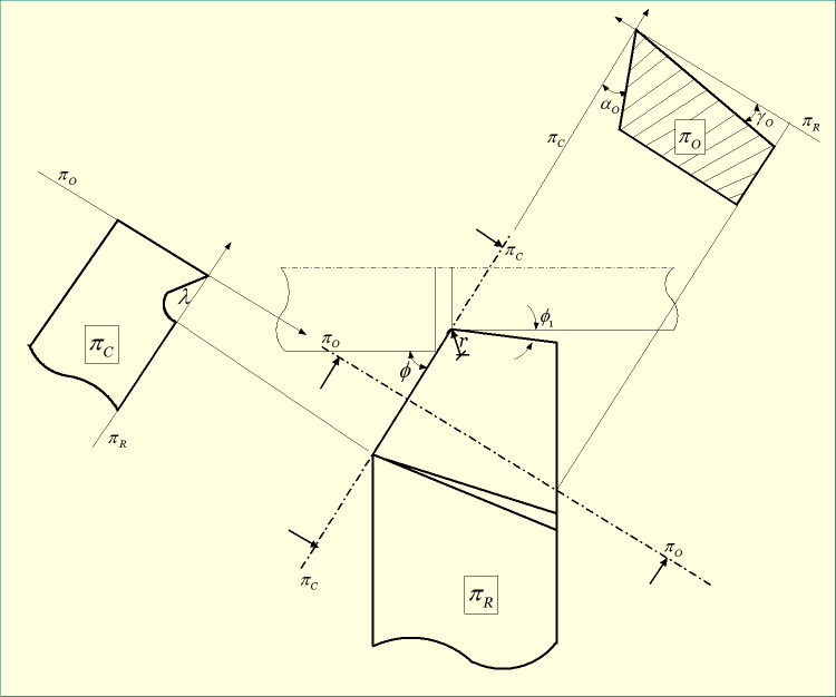
Planes used as reference in ORS system of tool designation
Orthogonal Rake System (ORS) utilizes three mutually perpendicular planes as reference for measuring various tool angles. These three planes are enlisted below.
- Reference Plane (πR)—It is a plane perpendicular to the cutting velocity vector (Vc).
- Cutting Plane (πC)—It is a plane perpendicular to reference plane (πR) and contains the principal cutting edge of the tool.
- Orthogonal Plane (πO)—It is a plane perpendicular to reference plane (πR) and also perpendicular to the cutting plane. So all three planes are mutually perpendicular (πO is perpendicular to both πR and πC).
Various features displayed in ORS system of tool designation
This system of tool designation specifies two different rake angles, two different clearance angles, two different cutting edge angles, and the nose radius value in mm. Various features of the single point turning tool (SPTT) that are specified in ORS system are enlisted below.
- Inclination Angle (λ)—It is the angle of inclination of tool’s principal cutting edge from the reference plane (πR) and measured on cutting plane (πC).
- Orthogonal Rake Angle (γO)—It is the angle of orientation of tool’s rake surface from the reference plane (πR) and measured on orthogonal plane (πO).
- Orthogonal Clearance Angle (αO)—It is the angle of orientation of tool’s principal flank surface from the cutting plane (πC) and measured on orthogonal plane (πO).
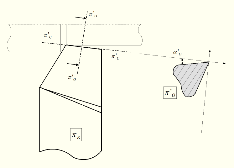
- Auxiliary Orthogonal Clearance Angle (αo’)—It is the angle of orientation of tool’s auxiliary flank surface from the auxiliary cutting plane (πC’) and measured on auxiliary orthogonal plane (πO’).
- Principal Cutting Edge Angle (Φ)—It is the angle between cutting plane (πC) (which contains principal cutting edge) and the longitudinal feed direction, measured on reference plane (πR).
- Auxiliary Cutting Edge Angle (Φ1)—It is the angle between auxiliary cutting plane (πC’) (which contains auxiliary cutting edge) and the longitudinal feed line, measured on reference plane (πR).
- Nose Radius (r)—This is nothing but the curvature at the tool tip. It is to be noted that in ORS system, nose radius value is expressed in mm.
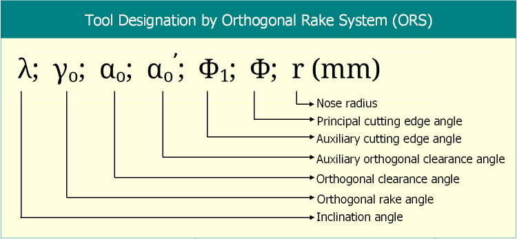
Tool nomenclature in ORS system
All the above mentioned seven features of the turning tool are specified in sequence as shown below. It is also called tool nomenclature. The sequence of designation should be followed strictly. However, different people may use different notations for various angles maintaining the original sequence unchanged.
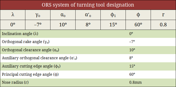
Example for ORS system of tool designation
Few points should be considered for giving examples of tool nomenclature. First and foremost one is the value of clearance angles. Clearance angles are always positive—it cannot be zero or negative. Usually it ranges from 3º – 15º. Also auxiliary cutting edge angle is usually lower than principal cutting edge angle; however, for thread cutting tool, they can be same. A zero inclination angle indicates ORS and NRS system are same. One example of ORS system of tool designation and interpretation of tool angles from such nomenclature is illustrated in the following figure.
Let us consider another example. Say, a typical turning tool can be specified in ORS system as:
–6º, –6º, 10º, 15º, 15º, 45º, 1.2 (mm)
Therefore, upon interpretation, we may write:
- Inclination Angle (λ) = –6º
- Orthogonal Rake Angle (γO) = –6º
- Orthogonal Clearance Angle (αO) = 10º
- Auxiliary Orthogonal Clearance Angle (αo’) = 15º
- Auxiliary Cutting Edge Angle (Φ1) = 15º
- Principal Cutting Edge Angle (Φ) = 45º
- Nose Radius (r) = 1.2 mm.
References
- Book: Principles of Mechanical Engineering by S. Singh (S. Shand).
- Book: Machining and Machine Tools by A. B. Chattopadhyay (Wiley).
- Book: Metal Cutting: Theory And Practice by A. Bhattacharya (New Central Book Agency).
- Book: Manufacturing Processes by J. P. Kaushish (PHI).
- Book: Manufacturing Science by M. I. Haque and S. Khan (PHI).