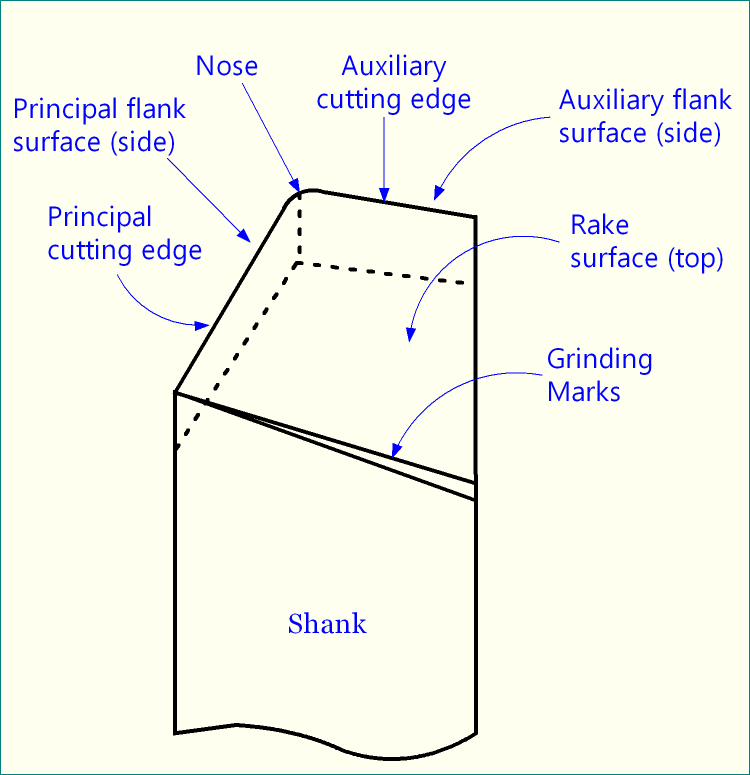
Geometry, orientation and material of the cutting tool are the three important factors that determine ease and performance of machining (machinability). Geometry of cutting tool consists of rake angles, clearance angles, auxiliary clearance angles, cutting angles and nose radius. All these angles basically express orientation of various surfaces of a turning tool. The three important surfaces of a single point turning tool (SPTT) are:
- Rake surface—chip flowing surface.
- Principal flank surface—remains in contact (for small length) with the machined / finished surface.
- Auxiliary flank surface—in some specific operations, it also remains in contact with the machined / finished surface.
Definition of clearance angle
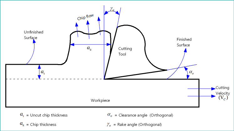
So the principal flank surface is the surface of ultimate interest as quality of the machined / finished surface depends a lot on its inclination and nature. The inclination of this principal flank surface is expressed with the help of clearance angles. By definition, clearance angle is the angle of orientation of tool’s principal flank surface from the cutting velocity vector (Vc) and measured on some other plane. Sometime, instead of using cutting velocity vector (Vc), cutting plane (πC) is used in definition as cutting plane itself contains cutting velocity vector.
Similarly, inclination of auxiliary flank surface is expresses by auxiliary clearance angles. By definition, Auxiliary clearance angle is the angle of orientation of tool’s auxiliary flank surface from the auxiliary cutting plane (πC’) and measured on some other plane.
Various names of clearance angles
Depending on the plane on which it is projected and measured, clearance angle have various names. An SPTT can be designated in various systems, such as American Standards Association (ASA) system, Orthogonal Rake System (ORS) or ISO old system, Normal Rake System (NRS) or ISO new system, and Maximum Rake System (MRS). Various systems use various names. Commonly used variants of clearance angle along with their definition are enlisted below.
Side Clearance Angle (αX)—It is the angle of orientation of tool’s principal flank surface from the cutting velocity vector (Vc) and measured on machine longitudinal plane (πX). It is used in ASA system of tool designation.
Back Clearance Angle (αY)—It is the angle of orientation of tool’s principal flank surface from the cutting velocity vector (Vc) and measured on machine transverse plane (πY). It is also used in ASA system of tool designation.
Orthogonal Clearance Angle (αO)—It is the angle of orientation of tool’s principal flank surface from the cutting plane (πC) and measured on orthogonal plane (πO). In turning, cutting plane is the plane that contains cutting velocity vector. It is used in ORS system of tool designation.
Auxiliary Orthogonal Clearance Angle (αo’)—It is the angle of orientation of tool’s auxiliary flank surface from the auxiliary cutting plane (πC’) and measured on auxiliary orthogonal plane (πO’). It is also used in ORS system of tool designation.
Normal Clearance Angle (αN)—It is the angle of orientation of tool’s principal flank surface from the cutting plane (πC) and measured on normal plane (πN). It is used in NRS system of tool designation.
Auxiliary Normal Clearance Angle (αN’)—It is the angle of orientation of tool’s auxiliary flank surface from the auxiliary cutting plane (πC’) and measured on auxiliary normal plane (πN’). It is also used in NRS system of tool designation.
Minimum Clearance Angle (αmin)—It is the angle of orientation of tool’s principal flank surface from the cutting plane (πC) and measured on a plane which is perpendicular to the master line for principal flank surface. As the name suggests, it provides the minimum value of principal clearance angle. It is beneficial while sharpening the cutting tool by grinding. This angle is required for designating an SPTT in MRS system.
Typical values of clearance angle
Clearance angle can never be negative or zero. Too small clearance angle will result intense rubbing and thus poor surface quality and smaller tool life. Too high clearance angle will make tool tip less strong and it may cause catastrophic failure of tool. Usually, value of clearance angle of the cutting tool varies in between +3º and +15º.
Functions of clearance angles in machining
In machining due to presence of small nose radius, the machined or finished surface rubs with the flank surface. Although length of the rubbing zone is tiny, it has significant effect on the finish and quality of the machined surface. The scallop or feed marks produced during actual cutting (or shearing) are compressed automatically due to this small rubbing action. So a smooth surface is obtained, which is desirable.
However, if clearance angle is very small then this contact length will be longer, and thus intense rubbing will happen which will generate high heat at that zone (known as tertiary deformation zone). This may cause surface burning, chatter marks, etc. that will destroy the machined surface. Intense rubbing will also increase tool wear rate (flank wear) and consequently reduce tool life and accuracy of cutting. Small clearance angle also makes the tool prone to plastic deformation. Therefore, an optimum value of clearance is highly desirable.
References
- Book: Principles of Mechanical Engineering by S. Singh (S. Shand).
- Book: Machining and Machine Tools by A. B. Chattopadhyay (Wiley).
- Book: Metal Cutting: Theory And Practice by A. Bhattacharya (New Central Book Agency).
- Book: Manufacturing Processes by J. P. Kaushish (PHI).
- Book: Manufacturing Science by M. I. Haque and S. Khan (PHI).