Abrasive jet machining (AJM) is one of the modern machining processes (mechanical energy based) where a high velocity jet of fine grain abrasives, mixed with compressed carrier gas, is utilized to erode material from work surface. AJM set-up comprises air compressor fitted with drier and cleaner, abrasive feeder and vibratory mixing chamber, nozzle, well ventilated machining chamber and various gauges for detecting pressure, flow rate, etc. A schematic diagram of such set-up is shown below. Functions of various components are also discussed below.
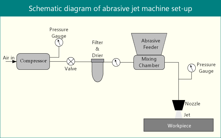
Components in AJM set-up and their functions
Air compressor
Usually air is sucked directly from atmosphere, it is first dried and made dust free and then compressed to high pressure. Carrier gas pressure is kept between 15 – 20bar, based on the compressor capacity and jet velocity requirement. Sometime commercially pure nitrogen or carbon di-oxide gas is also used to obtain better result for some specific cases.
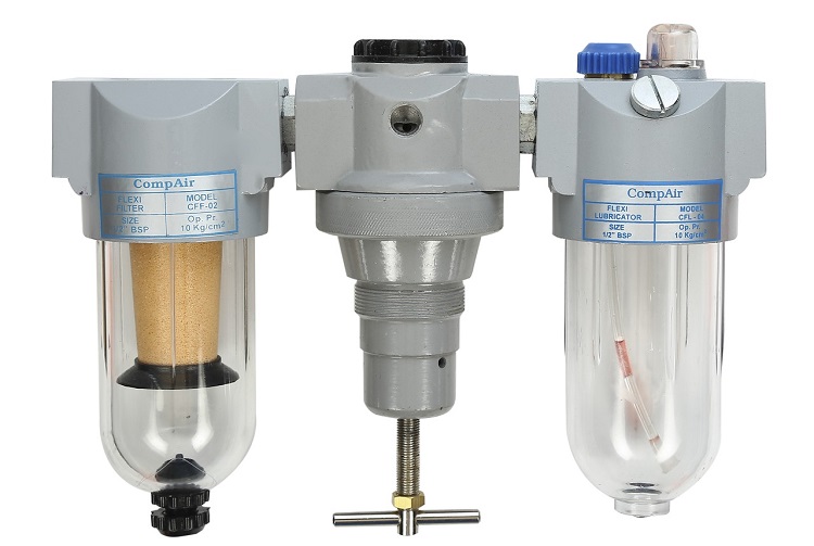
FRL unit
High pressure air is passed through filter regulator lubricating (FRL) unit to remove any suspended particles such as dust or oil. Commonly compressor is fitted with FRL unit to make the carrier gas dry and dust free. Presence of steam in compressed gas is highly undesirable as it can coagulate and can cause agglomeration of abrasives during flow through pipelines.
Pressure regulator and flow valve
As the names suggest, compressed carrier gas pressure has to be regulated properly as final jet velocity relies on it. Flow rate is also crucial parameter that can affect erosion rate (or MRR) via mixing ratio.
Abrasive feeder and mixing chamber
Fine grain abrasive powders initially maintained at atmospheric pressure at primary chamber are allowed to flow to secondary chamber and then to the mixing chamber under the assistance of low amplitude vibration. Compressed carrier gas is also passed through this mixing chamber and thus momentum transfer takes place between gas and abrasives. So abrasives gain momentum in terms of velocity and start flowing with carrier gas through the pipeline. During mixing, the predefined mixing ratio is maintained by the amplitude and frequency of the vibration and pressure of compressed gas has no influence on it. Flow and pressure regulating valves are also employed here to control flow rate and pressure of gas-abrasive mixture.
Nozzle
Gas-abrasive mixture is directed towards nozzle, which converts the hydraulic energy (pressure) into kinetic energy and thus a high velocity abrasive jet is obtained. The nozzle is kept at a particular distance over the work surface. Thus gap is termed as stand-off distance (SOD) and it is a paramount factor that governs machining accuracy. Inclination angle, the angle between work surface and jet axis, is also controlled by orientating the nozzle. Moreover, nozzle is mounted on a slider to impart necessary motions as per the required profile of cut.
Working chamber
A closed working chamber is indispensably necessary to avoid pollution. Workpiece, mounted by fixtures, is placed within this chamber. A vacuum cleaner is connected to the working chamber for removing tiny suspended abrasives from air before discharging it to atmosphere.
Modern accessories and controlling
Now-a-days abrasive jet machining set-up is integrated with timers, numerous sensors, pneumatic controller, and also CNC. One such timer can accurately control duration of blast. Sensors can be utilized to detect pressure and flow rate at inlet and outlet of nozzle. Such sensor readings are helpful in predictive maintenance and timely replacement of worn out nozzle as well as to avoid any inaccuracy in machining. Computer numerical control (CNC) system with the help of stepper motor is also used to precisely position the nozzle and control various movements.
References
- Paper: M. W. Chastagner and A. J. Shih, Abrasive jet machining for edge generation, Transactions of NAMRI/SME, Vol. 35, 2007.
- Paper: A P. Verma and G. K. Lal; An experimental study of abrasive jet machining; International Journal of Machine Tool Design and Research; Vol. 24; pp. 19-29; 1984.
- Paper: N. Ramachandran and N. Ramakrishnan; A review of abrasive jet machining; Journal of Materials Processing Technology; Vol. 39; pp. 21-31; 1993.