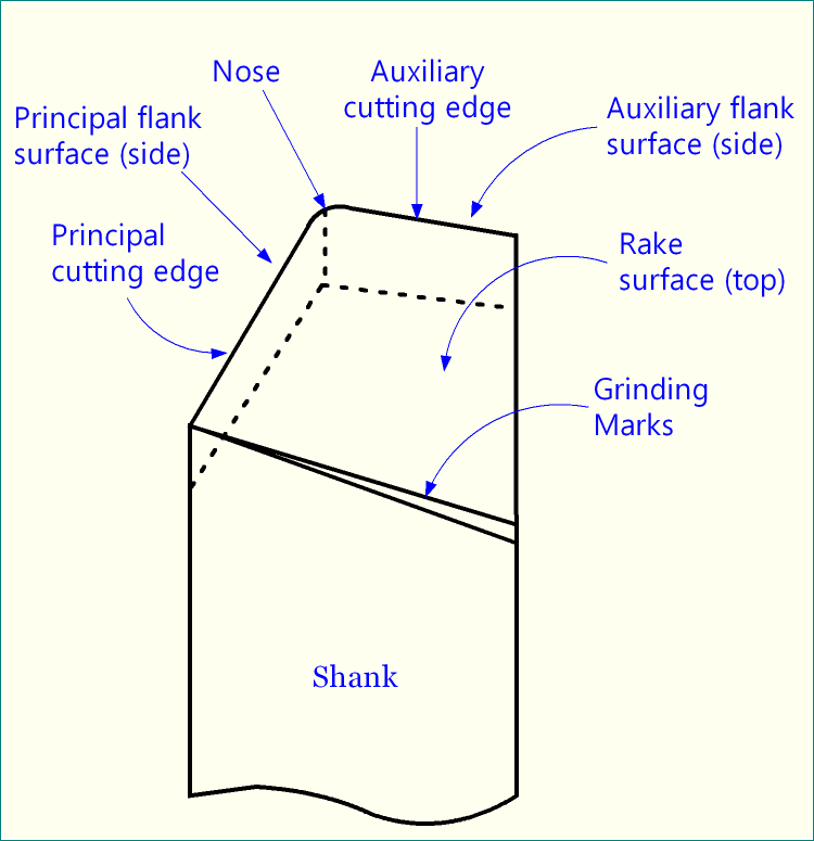
Geometry, orientation and material of the cutting tool are the three important factors that determine ease and performance of machining (machinability). Geometry of cutting tool consists of rake angles, clearance angles, auxiliary clearance angles, cutting angles and nose radius. All these angles basically express orientation of various surfaces of a turning tool. The three important surfaces of a single point turning tool (SPTT) are:
- Rake surface—chip flowing surface.
- Principal flank surface—remains in contact (for small length) with the machined / finished surface.
- Auxiliary flank surface—in some specific operations, it also remains in contact with the machined / finished surface.
Nose radius in turning tool
The point of intersection of three tool point surfaces gives rise to the tool tip. Since tool tip is subjected to the severe cutting force during machining, so any sharp point may break quickly. In order to avoid catastrophic failure of tool tip, a tiny rounding or small radius is provided there, which is known as nose radius. By definition, nose radius is the radius value at the tip of the cutting tool, measured on reference plane (πR).
Values of nose radius
The radius value for conventional single point turning tool (SPTT) usually ranges between 0.6 – 1.5mm. For precision tools, this nose radius value may be very small in the range of few microns only.
Nose radius value is also presented in tool designation. An SPTT can be designated in various systems, such as American Standards Association (ASA) system, Orthogonal Rake System (ORS) or ISO old system, Normal Rake System (NRS) or ISO new system, and Maximum Rake System (MRS). ASA system displays nose radius value in inch unit; whereas, ORS and NRS systems display the value in mm unit.
Advantages of providing nose radius in cutting tool
- Prevents tool tip from sudden unplanned breakage.
- Absorbs and distributes shock during impact loading in machining.
- Offers a small amount of rubbing between flank surface and machined surface, which leads to better finish of the machined surface.
- Easier to manufacture, very sharp edge cannot be manufactured efficiently.
- Easy manufacturing also results in cheaper tool.
Disadvantages of providing nose radius in cutting tool
- Increase in cutting force and power consumption.
- Larger heat generation.
- Changes chip flow direction.
- Prevents obtaining high surface finish.
- No cutting action or chip formation (usually in micro-machining) if depth of cut is substantially lower than nose radius.
References
- Book: Principles of Mechanical Engineering by S. Singh (S. Shand).
- Book: Machining and Machine Tools by A. B. Chattopadhyay (Wiley).
- Book: Metal Cutting: Theory And Practice by A. Bhattacharya (New Central Book Agency).
- Book: Manufacturing Processes by J. P. Kaushish (PHI).
- Book: Manufacturing Science by M. I. Haque and S. Khan (PHI).