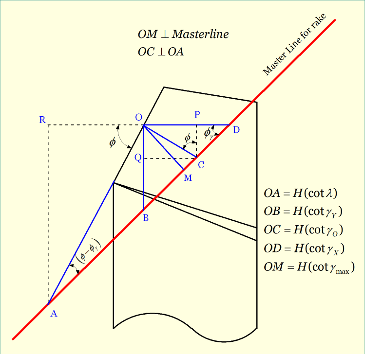
Rake angle is the measure of inclination of the rake surface from reference plane in various directions. Value of rake angle changes based on the direction it is measured. In a particular direction, value of rake angle is maximum; correspondingly, in a particular direction rake angle is zero (not necessarily minimum). Master line plays crucial role in determining this direction. Basically, along the master line the rake angle is zero, while in a direction perpendicular to master line the rake angle is maximum. This maximum rake angle has many advantages, especially during re-sharpening the uncoated tool using 3-D vice as discussed in the following sections.
Definition of Maximum Rake Angle (γmax)
It is the angle of orientation of tool’s rake surface from the reference plane (πR) and measured on a plane which is perpendicular to the master line for rake surface. As the name suggests, it provides the maximum value of rake angle for a particular cutting tool. This angle is used in Maximum Rake System (MRS) of cutting tool designation.
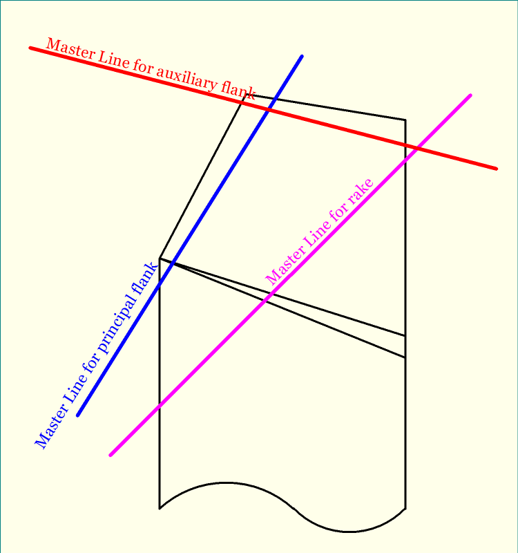
Basically, Master Line is the line of intersection between the reference plane (πR) and any one of the three tool point surfaces. For an SPTT, there exist three tool point surfaces—rake surface, principal flank surface and auxiliary flank surface. Consequently, three master lines can be obtained for a turning tool.
- Master Line for Rake Surface—It is the line of intersection between the Reference Plane (πR) and Rake surface of the cutting tool.
- Master Line for Principal Flank Surface—It is the line of intersection between the Reference Plane (πR) and Principal Flank surface of the cutting tool.
- Master Line for Auxiliary Flank Surface—It is the line of intersection between the Reference Plane (πR) and Auxiliary flank surface of the cutting tool.
Concept of MRS system of tool designation
There are various systems for designation of turning tool geometry, each has specific advantages and disadvantages. Among various systems, the commonly used systems for turning tool designation are—
- Tool In Hand System
- American Standards Association (ASA) system
- Orthogonal Rake System (ORS) or ISO Old System
- Normal Rake System (NRS) or ISO New System
- Maximum Rake System (MRS)
Although Maximum Rake System (MRS) System is not properly a tool designation system, it takes into account some important features of the cutting tool, including the maximum rake angle, minimum clearance angle and setting angles. The below figure shows the maximum rake angle and setting angle for rake surface of a turning tool, which are used in MRS system.
Advantages of using maximum rake angle
- While grinding single point turning tool (SPTT), if ASA, ORS or NRS system is employed then 3-D vice is required and the cutting tool needs to set for three different angles. However, if MRS system is employed then only two angle settings are sufficient for grinding rake surface—the maximum rake angle and setting angle for rake surface. So a 2-D vice can be employed.
- Due to this advantage, tool grinding/sharpening becomes easier, cheaper and quicker.
References
- Book: Machining and Machine Tools by A. B. Chattopadhyay (Wiley).
- Book: Metal Cutting: Theory And Practice by A. Bhattacharya (New Central Book Agency).