Various features of a cutting tool including rake angles, clearance angles, cutting angles and nose radius can be displayed in a specific manner in the tool signature. Tool designation systems basically specify the manner of displaying a tool signature. There exist quite a few tool designation systems as enlisted below. Maximum Rake System (MRS) in one of such tool designation systems, which offers many advantages over other systems of specifying tool signature. A detail discussion on maximum rake system is presented in the subsequent sections.
- Tool In Hand system
- American Standards Association (ASA) system
- Orthogonal Rake System (ORS) or ISO Old System
- Normal Rake System (NRS) or ISO New System
- Maximum Rake System (MRS)
What is Maximum Rake System (MRS) of tool designation?
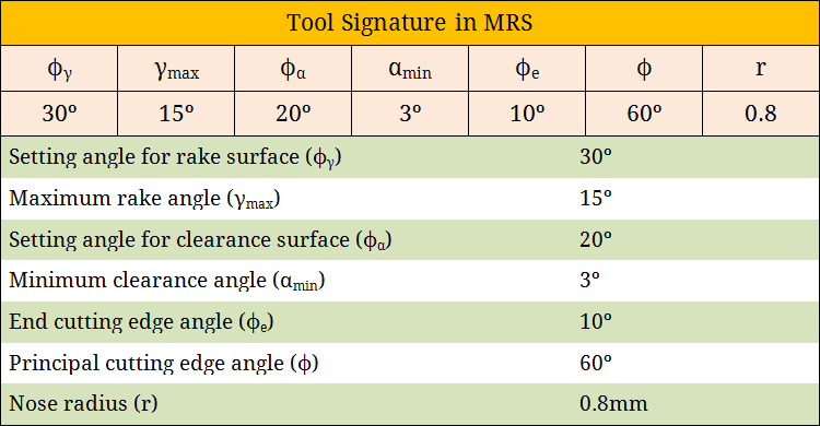
Maximum Rake System (MRS) displays maximum rake angle (γmax) and minimum clearance angle (αmin) of the cutting tool in its signature. As the name suggests, maximum rake angle provides the direction at which the inclination of rake surface of the tool is maximum. Similarly, minimum clearance angle provides the direction at which the inclination of principal flank surface of the tool is minimum. Apart from the maximum rake and minimum clearance, MRS tool signature also displays setting angles for rake and clearance surfaces. These angles are indispensably necessary while grinding tool surfaces using 2-D vice. Tool signature as per MRS system is depicted below.
Various features of tool covered in MRS system
Various features of the single point turning tool (SPTT) that MRS system specifies are provided below. Typical definitions of such features are also given here.
- Maximum Rake Angle (γmax)—It is the angle of orientation of tool’s rake surface from the reference plane (πR) and measured on a plane which is perpendicular to the master line for rake surface. As the name suggests, it provides the maximum value of rake angle for a particular turning tool.
- Minimum Clearance Angle (αmin)—It is the angle of orientation of tool’s principal flank surface from the cutting plane (πC) and measured on a plane which is perpendicular to the master line for principal flank surface. As the name suggests, it provides the minimum value of principal clearance angle.
- Setting Angle for Rake (Φγ)—It is the angle between master line of rake surface and the machine longitudinal plane (πX).
- Setting Angle for Flank (Φα)— It is the angle between master line of principal flank surface and the machine longitudinal plane (πX).
Advantages of Maximum Rake System (MRS)
Although MRS System does not clearly display various salient features of a turning tool, this system is advantageous while sharpening or grinding the conventional turning tools (uncoated). While grinding single point turning tool (SPTT), if ASA, ORS or NRS system is employed then 3-D vice is required and the cutting tool is required to set for three different angles.
However, if MRS system is employed for such purpose then only two angle settings are sufficient for grinding one surface of the cutter (such as for rake surface—the maximum rake angle and setting angle are sufficient). So a 2-D vice can be employed. This advantage makes the tool grinding or sharpening process more efficient, easier and quicker.
Disadvantages of Maximum Rake System (MRS)
Maximum rake angle (γmax) and minimum clearance angle (αmin) of the cutting tool cannot be measured directly by using instrument or apparatus. However, such angles can be calculated from other values, especially from tool angles of either ASA or ORS. So if tool signature in ASA or ORS is unknown then writing signature in MRS is not possible. It is to be noted that MRS features other than γmax and αmin can be measured directly.
Obtaining MRS tool angles from ORS/ASA systems
Since all tool angles of MRS system are not measurable, so angles are required to calculate from the known angle values in ORS or ASA system. The following expressions can be used for calculation purposes. Such expressions can be obtained via tool angle conversion (mainly via Master Line principle).
- \({\left( {\tan {\gamma _{\max }}} \right)^2} = {\left( {\tan {\gamma _X}} \right)^2} + {\left( {\tan {\gamma _Y}} \right)^2}\)
- \({\left( {\tan {\gamma _{\max }}} \right)^2} = {\left( {\tan \lambda } \right)^2} + {\left( {\tan {\gamma _O}} \right)^2}\)
- \(\tan {\phi _\gamma } = {{\left( {\tan {\gamma _X}} \right)} \over {\left( {\tan {\gamma _Y}} \right)}}\)
- \(\tan \left( {\phi – {\phi _\gamma }} \right) = {{\left( {\tan \lambda } \right)} \over {\left( {\tan {\gamma _O}} \right)}}\)
- \({\left( {\cot {\alpha _{\min }}} \right)^2} = {\left( {\tan \lambda } \right)^2} + {\left( {\cot {\alpha _O}} \right)^2}\)
- \(\tan \left( {\phi – {\phi _\alpha }} \right) = {{\left( {\tan {\alpha _O}} \right)} \over {\left( {\cot \lambda } \right)}}\)
References
- Book: Principles of Mechanical Engineering by S. Singh (S. Shand).
- Book: Machining and Machine Tools by A. B. Chattopadhyay (Wiley).
- Book: Metal Cutting: Theory And Practice by A. Bhattacharya (New Central Book Agency).
- Book: Manufacturing Processes by J. P. Kaushish (PHI).
- Book: Manufacturing Science by M. I. Haque and S. Khan (PHI).