Various features of a cutting tool when specified in an abridged but standardized manner are termed as tool signature. Therefore, tool signature provides various static geometrical details of that particular cutting tool, especially various angles and nose radius. Commonly, it provides values of rake angles, clearance angles, cutting edge angles, nose radius, etc. There are various standard systems for designation of a cutting tool, each having pros and cons over another. A single point cutting tool may have different tool signatures based on the system of designation. Different types of tool also have different designation systems; however, here designation and signature of single point turning tool is discussed.
Systems for specifying cutting tool signature
Single point cutting tools are such cutters that contain only one main cutting edge that can participate in cutting action in a single pass. Examples include turning, boring, shaping, planing, and slotting tools. There exist three conventional systems for designation of such cutting tools, as enlisted below. A particular tool can be specified by all three systems and correspondingly tool signatures will also be different. Different tool signature does not indicate the tool angles are different; instead, it indicates inclination of a surface in different directions.
- American Standards Association (ASA) system
- Orthogonal Rake System (ORS)
- Normal Rake System (NRS)
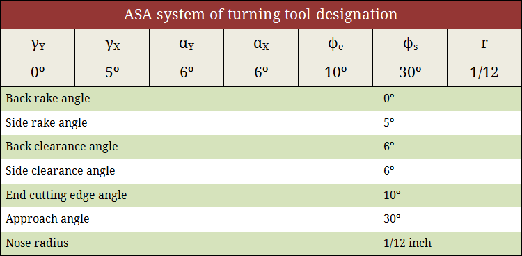
Tool signature in ASA system
American Standards Association (ASA) system utilizes three mutually perpendicular planes for reference purpose namely Machine longitudinal plane, Machine transverse plane and Reference plane. Tool signature in ASA system consists of two rake angles, two clearance angles, two cutting edge angles and the nose radius of a single point cutting tool. The sequence of writing tool signature in ASA system along with the name of various angles is depicted below. It is to be noted that different persons may use different symbol but the sequence must be maintained. A typical example is also provided below. Learn more about ASA system.
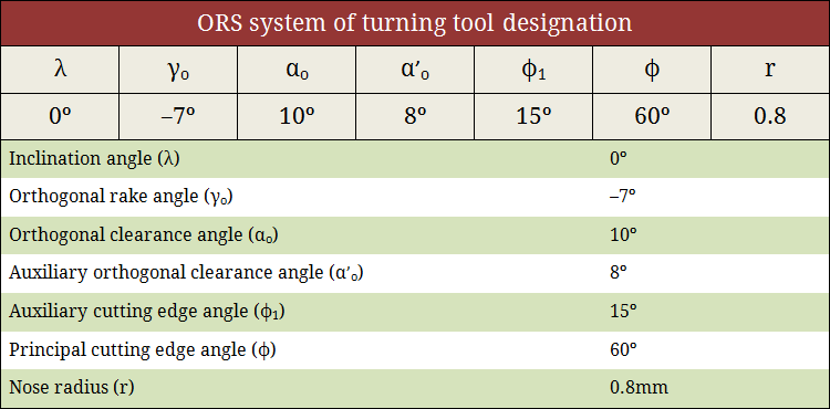
Tool signature in ORS system
Orthogonal Rake System (ORS) also utilizes three mutually perpendicular planes for reference purpose namely Cutting plane, Orthogonal plane and Reference plane. Similar to the ASA system, tool signature in ORS system consists of two rake angles, two clearance angles, two cutting edge angles and the nose radius of a single point cutting tool. Note that in ASA system, nose radius is measured in inch unit; whereas, in ORS system it is measured in mm. The sequence of writing tool signature in ORS system along with the name of various angles is depicted below. As usual, the sequence cannot be altered but alternative notation can be used. A typical example is also provided below. Learn more about ORS system.
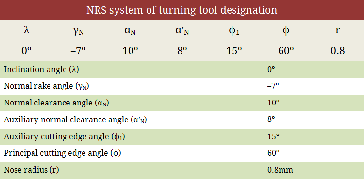
Tool signature in NRS system
Normal Rake System (NRS) utilizes three planes (not necessarily mutually perpendicular) for reference purpose namely Cutting plane, Normal plane and Reference plane. Similar to the ORS system, tool signature in NRS system also consists of two rake angles, two clearance angles, two cutting edge angles and the nose radius of a single point cutting tool. The following images show the tool signature in NRS system and the way to retrieve values of various angle from the given tool signature. Learn more about NRS system.
References
- Book: Principles of Mechanical Engineering by S. Singh (S. Shand).
- Book: Machining and Machine Tools by A. B. Chattopadhyay (Wiley).
- Book: Metal Cutting: Theory And Practice by A. Bhattacharya (New Central Book Agency).
- Book: Manufacturing Processes by J. P. Kaushish (PHI).
- Book: Manufacturing Science by M. I. Haque and S. Khan (PHI).