A tool signature displays various features of a cutting tool in an abridged but standardized form. Because of the availability of different tool designation systems for writing a tool signature, one needs to know that particular system for interpreting it. Since different tool designation systems utilize different features of the tool for expressing tool signature, so a particular cutting tool may have different versions of tool signature based on the system followed for writing it.
Single point cutting tools (like turning tool, shaping tool, boring tool, planing tool, etc.) can be designated in three different ways—American Standards Association (ASA) system, Orthogonal rake System (ORS) and Normal Rake System (NRS). Each of them has certain advantages over other two. A comparison among these three systems of tool designation is discussed below.
Planes used for reference purpose
- ASA system—It utilizes three mutually perpendicular planes namely Machine longitudinal plane, Machine transverse plane and Reference plane. Reference plane is a plane perpendicular to cutting velocity vector in turning. Machine longitudinal plane is perpendicular to reference plane and is along longitudinal axis of lathe. As the name suggests, machine transverse plane is along the transverse axis of the lathe and is perpendicular to other two planes.
- ORS system—It also utilizes three mutually perpendicular planes namely Reference plane, Cutting plane, and Orthogonal plane. As usual, reference plane is a plane perpendicular to cutting velocity vector in turning. Cutting plane contains principal cutting edge of the tool and is perpendicular to reference plane. Orthogonal plane is perpendicular to other two planes.
- NRS system—It also utilizes three planes for reference purpose (Reference plane, Cutting plane, and Normal plane) but they may not be mutually perpendicular. Here normal plane is a plane perpendicular to the principal cutting edge and is inclined with the orthogonal plane by an angle equals to inclination angle (λ) of the tool. So if λ = 0º, then both normal plane and orthogonal plane will coincide.
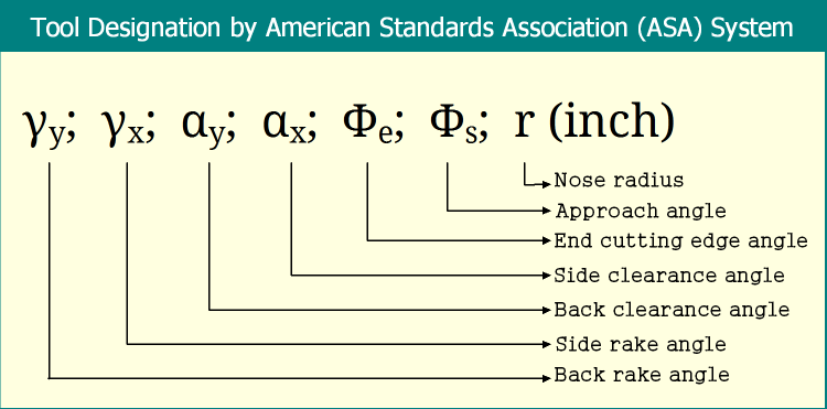
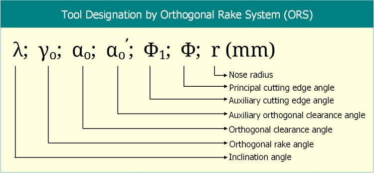
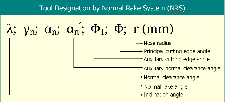
Tool designation in three systems
All three systems of turning tool designation express tool signature in different ways. Various angles expressed by these three tool designation systems are depicted below. All the images are self-explained.
Unit of nose radius in tool signature
As shown in above diagrams, ASA system expresses nose radius of the cutting tool in inch unit; whereas ORS and NRS express the same feature in mm unit.
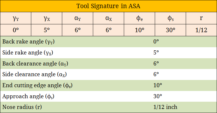
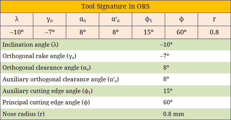
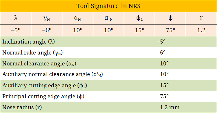
Tool signature interpretation
As displayed below, tool signature can be interpreted by comparing it with the standard designation style. While comparison, note that you are utilizing same system and the sequence is properly maintained. The following images show how to interpret tool signature for obtaining various angles. Tool angles in one system can also be further converted into angles of other systems.
Features of auxiliary flank surface displayed in tool signature
ASA system displays the angle between auxiliary cutting edge and machine longitudinal plane using end cutting edge angle but it does not reveal any information about the inclination of auxiliary flank surface. On the other hand, ORS and NRS provide some information about it using auxiliary clearance angles (orthogonal/normal).
Relative advantages and disadvantages
ASA system is advantageous particularly in measuring the tool angles for inspection. ORS is commonly used in various analyses (especially when orthogonal machining is assumed) including estimation of cutting force, judging machinability and performance on machining. However, while setting the angles in a 3-D vice for re-sharpening the cutting tool by grinding, if ORS system is followed then further angle corrections are required (if the tool has non-zero inclination angle). These limitations can be eliminated by employing NRS system.
References
- Book: Principles of Mechanical Engineering by S. Singh (S. Shand).
- Book: Machining and Machine Tools by A. B. Chattopadhyay (Wiley).
- Book: Metal Cutting: Theory And Practice by A. Bhattacharya (New Central Book Agency).
- Book: Manufacturing Processes by J. P. Kaushish (PHI).
- Book: Manufacturing Science by M. I. Haque and S. Khan (PHI).