Material, geometry and setting orientation of cutting tool are three paramount factors that influence machining capability and overall machining performance (machinability). Geometry of a cutting tool encompasses inclination and orientation of various planes and cutting edges of the tool as well as nose radius. Tool designation basically refers displaying various features of the cutting tool in a symbolic but standardized manner. There are various tool designation systems and each has specific style of representing such features. Necessity of designating a tool as well as various designation systems and corresponding tool signature are discussed in the following sections.
Necessity for designating a cutting tool
Most of the tool designation systems are standardized. As usual, a standardized tool signature helps choosing the most suitable tool for a particular application. Apart from selection, it also facilitates fast and easy interpretation of various features, quick replacement, straightforward design, facile generalizations and also better planning, estimation and control.
Various systems of turning tool designation
There are various systems for designation of single point turning tool, each has specific advantages and disadvantages. Among various systems, the commonly used systems for turning tool designation are enlisted below.
- Tool In Hand system
- American Standards Association (ASA) system
- Orthogonal Rake System (ORS) or ISO Old System
- Normal Rake System (NRS) or ISO New System
- Maximum Rake System (MRS)
Tool In Hand system of tool designation
Tool designation by Tool-In-Hand system basically refers to the identification of few useful salient features just by observing the cutting tool in bare eyes. Usually, it does not fetch any quantitative value (like value of principal cutting edge angle is 60º); rather it gives apparent and generalized information of the tool. Such views are immensely helpful in selecting a particular tool prior to operation. For example, the Tool-In-Hand system for turning tool can provide following information relevant to the cutter. Read details about tool-in-hand system.
- Right hand tool or left hand tool.
- What are rake surface, principal flank surface and auxiliary flank surface?
- What is tool nose?
- What type of shank it has?
- Sometime, coated or uncoated.
- Insert based or plain.
- Basic tool material, if engraved in tool body.
ASA system of tool designation
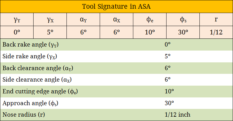
In American Standards Association (ASA) system, turning tool angles are designated based on machine longitudinal plane and machine transverse plane along with reference plane. It consists of two rake angles, two clearance angles, two cutting angles and the nose radius of the turning tool. The nose radius value is expresses in inch. There exists a specific pattern for designation of turning tool by ASA system as provided below. It is to be noted that ASA system does not portray any information about the auxiliary cutting plane of the turning tool. Learn more about American Standards Association (ASA) system.
ORS system of tool designation
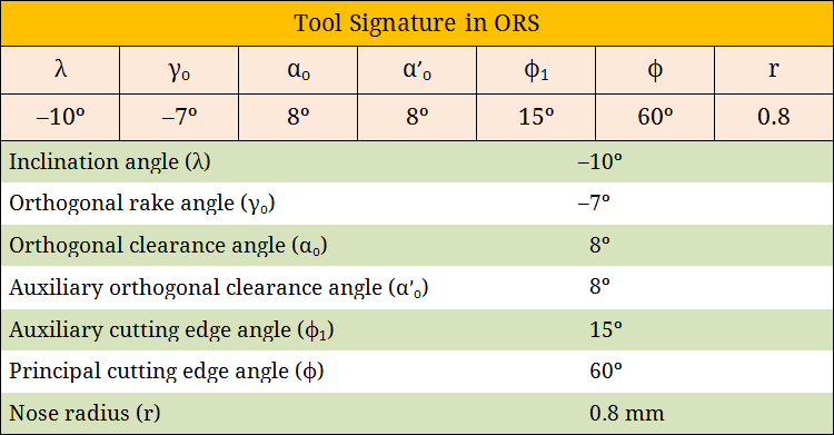
In Orthogonal Rake System (ORS), also called ISO Old System, orthogonal plane and cutting plane along with reference plane are utilized for designation of turning tool geometry. The ORS system displays two rake angles—two clearance angles two cutting angles and the nose radius (value in mm). Unlike ASA system, ORS system provides some information regarding the orientation of auxiliary cutting plane of an SPTT. Learn more about Orthogonal Rake System (ORS).
NRS system of tool designation
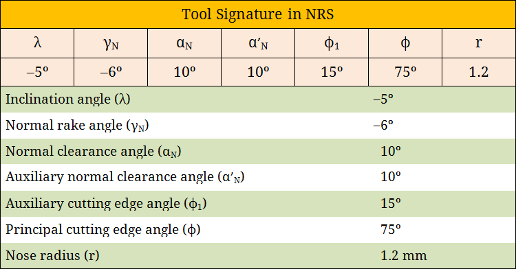
In Normal Rake System (NRS), also called ISO New System, normal plane and cutting plane along with reference plane are utilized for designation of turning tool geometry. NRS system displays two rake angles, two clearance angles, two cutting angles and the nose radius value in mm. Unlike ASA system, NRS system also provides some information regarding the orientation of auxiliary cutting plane of the SPTT. Learn more about Normal Rake System (NRS).
Although NRS and ORS systems look similar, NRS system has few specific advantages over the other one. Moreover, when inclination angle of the cutting tool is zero, ORS and NRS systems become similar. In fact, the angle between orthogonal plane (in ORS system) and normal plane (in NRS system) is equal to inclination angle of the tool.
- Difference between ORS system and NRS system.
- When ORS system and NRS system will be same?
- Comparison among ASA, ORS and NRS systems of tool designation.
MRS system of tool designation
Maximum Rake System (MRS) of tool designation, also called British System, uses maximum rake angle and minimum clearance angle to describe a tool. Compared to other standard designation systems, MRS system offers certain advantages during setting the tool in vice for grinding or sharpening operation. In either of the above three systems (ASA, ORS and NRS), at least three angles are required to set for grinding of each face of the tool; whereas, MRS needs setting of only two angles for each surface. So instead of using 3-D vice, a 2-D vice will be sufficient. This reduces difficulty and saves time for re-sharpening uncoated tools.
References
- Book: Principles of Mechanical Engineering by S. Singh (S. Shand).
- Book: Machining and Machine Tools by A. B. Chattopadhyay (Wiley).
- Book: Metal Cutting: Theory And Practice by A. Bhattacharya (New Central Book Agency).
- Book: Manufacturing Processes by J. P. Kaushish (PHI).
- Book: Manufacturing Science by M. I. Haque and S. Khan (PHI).