In conventional machining, excess material is removed from work surface using a wedge shaped sharp edged cutting tool. Such cutting edge is basically obtained by the intersection of two surfaces. Every cutting tool consists of two or more tool point surfaces, which also include rake surface and flank surface. Thus flank surface is one of the tool point surfaces that produces cutting edge by intersection with rake surface.
What is flank surface in a cutting tool?
Beside rake surface, every cutting tool should have at least one flank surface. The intersection of flank surface and rake surface produces the cutting edge and this cutting edge actually removes excess material from the workpiece in order to fulfill ultimate objective of machining or metal cutting operation.
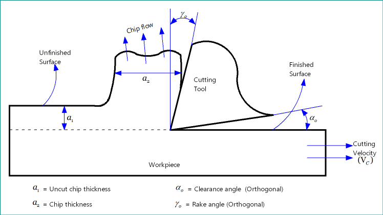
Rake surface inclined towards unmachined surface and chips; while, clearance surface is inclined towards finished surface of the job. Since chips flow over the rake surface of the cutting tool so this surface always remains in physical contact, which leads to excessive wear and heat generation. On the contrary, flank surface always remains free from any contact, except at the tiny portion at tip due to edge radius. Thus flank surface is less vulnerable under wear. You may also read: Difference between rake surface and flank surface.
How many flank surfaces a cutting tool contain?
A cutting tool may have one or more flank surfaces. It is worth noting that total number of flank surfaces present in a cutting tool depends on the number of cutting edges. A single point cutter contains only one flank surface; while, a multi-point cutter contains multiple (equals to number of cutting edges) flank surfaces. Therefore, for every cutting edge there will be one main flank surface.
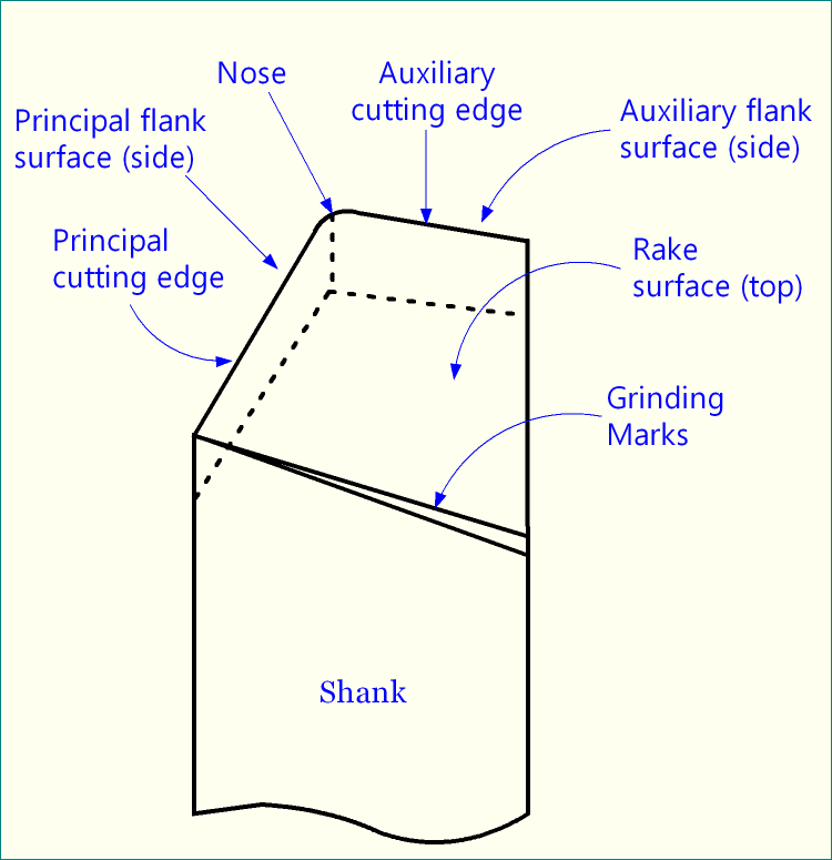
Many single point cutters contain two flank surfaces – one principal and another one auxiliary. For example, two flank surfaces of a single point turning tool (SPTT) are:
- Principal flank surface—remains in contact (for small length) with the machined / finished surface. Intersection of rake surface and principal flank surface produces main cutting edge.
- Auxiliary flank surface—in some specific operations, it also remains in contact with the machined / finished surface. Intersection of rake surface and auxiliary flank surface produces auxiliary cutting edge.
Inclination of flank surface – Clearance angle
The inclination of flank surface is expressed with the help of clearance angles. By definition, clearance angle is the angle of orientation of tool’s flank surface from the cutting velocity vector (Vc) and measured on some other plane. Sometime, instead of using cutting velocity vector (Vc), cutting plane (πC) or other suitable plane is used in definition as cutting plane itself contains cutting velocity vector.
Depending on the plane on which it is projected and measured, clearance angle may have various names. For example, an SPTT can be designated in various systems, such as American Standards Association (ASA) system, Orthogonal Rake System (ORS) or ISO old system, Normal Rake System (NRS) or ISO new system, and Maximum Rake System (MRS). Various systems use various names.
Flank surface may be flat or curve
Flank surface may not necessarily flat. Depending on the cutting tool, it may be a flat surface (do not confuse with horizontal) or a curve one. For example, the flank surface of single point turning tool (SPTT) is flat; whereas, that of a drill is a curve one.
References
- Book: Principles of Mechanical Engineering by S. Singh (S. Shand).
- Book: Machining and Machine Tools by A. B. Chattopadhyay (Wiley).
- Book: Metal Cutting: Theory And Practice by A. Bhattacharya (New Central Book Agency).
- Book: Manufacturing Processes by J. P. Kaushish (PHI).
- Book: Manufacturing Science by M. I. Haque and S. Khan (PHI).