Question: While turning a 60 mm diameter bar, it was observed that the tangential cutting force was 3000 N and the feed force was 1200 N. If the tool rake angle is 32°, then calculate the coefficient of friction. [ESE 2018]
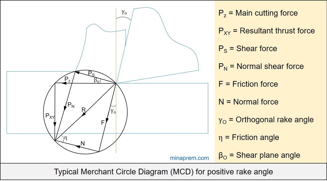
Solution: This problem can be solved with the help of Merchant Circle Diagram (MCD). In orthogonal machining of ductile material with a single point turning tool, the relevant forces can be displayed altogether in the MCD. So MCD is the vectorial representation of various force components under orthogonal machining. Here, it is not mentioned whether orthogonal or oblique cutting, so let us assume this is the case of orthogonal machining. The orthogonal rake angle is given as +32°. A typical MCD for positive rake is given below.
The feed force given in the question actually indicates the resultant thrust force (PXY). Therefore, the tangential or main cutting force (PZ) and resultant thrust force (PXY) are provided. Using these two values, the angle between PZ and R can be calculated. Again, the rake angle is given. So the angle between R and F can be calculated. Using this value, the friction angle can be calculated, the tangent of which gives the coefficient of friction. Step by step solution of the problem is given below.
Step-1: Find out angle between PZ and R
The triangle constituted by PZ, PXY and R is one right angle triangle as R is the diameter of the Merchant’s circle. Here the values of PZ and PXY are known. So consider the right angle triangle constituted by PZ, PXY and R. If the angle between PZ and R is considered as θ, then:
\[\tan \theta = \frac{{{P_{XY}}}}{{{P_Z}}}\]
\[\tan \theta = \frac{{1200}}{{3000}} = \frac{2}{5}\]
\[\theta = {\tan ^{ – 1}}\left( {\frac{2}{5}} \right) = 21.8^\circ \]
Step-2: Find out friction angle (η)
Angle between PZ and R = 21.8°
Angle between πR and F = Rake angle = +32° [πR indicates the reference plane, which is perpendicular to cutting velocity vector. Since force component PZ is along the cutting velocity vector, so πR is also perpendicular to PZ. In fact, the angle between πR and rake surface is basically the rake angle]
Therefore, the angle between the R and F = 90° – 21.8° – 32° = 36.2°
Now once again consider the right angle triangle constituted by R, F and N. The angle between R and N is the friction angle (η). The angle between the R and F is calculated earlier is equal to 36.2°. Thus the value of friction angle is:
Friction angle (η) = 90° – 36.2° = 53.8°
Step-3: Calculate coefficient of friction (μ)
Tangent of friction angle gives the coefficient of friction. So from the known value of friction angle, the coefficient of friction can be calculated easily as given below.
\[\mu = \tan \eta \]
\[\mu = \tan 53.8 = 1.37\]
Therefore, the coefficient of friction between the chip tool interface is 1.37. It is worth noting that the coefficient of friction in this case is higher than 1. Although this is not impossible, but it indicates that the friction force is stronger than normal force. The possible consequence might be longer chip-tool contact area, excessive heat generation and accelerated wear. The coefficient of friction in this case can be reduced by reducing rake angle. Here the rake angle is +32°, which is very high positive rake. Typically rake angle exists in between -15° to +15°. So there is a provision to cut down the coefficient of friction.