Question: During orthogonal turning operation of a hollow cylindrical pipe, it is found that the thickness of the chip produced is 0.5mm. The feed given to the zero degree rake angle tool is 0.2mm/rev. Calculate the shear strain produced during the operation? [GATE 2014]
Solution: Cutting stain indicates the shear strain developed during any conventional machining operation due to the shearing of one thin layer of workpiece material over another layer under the action of cutting tool. Such shearing ultimately produces intended chip. In orthogonal machining with a sharp tool, the cutting strain (ε) can be expressed in terms of shear angle (βO) and orthogonal rake angle (γO) of the cutting tool, as displayed below.
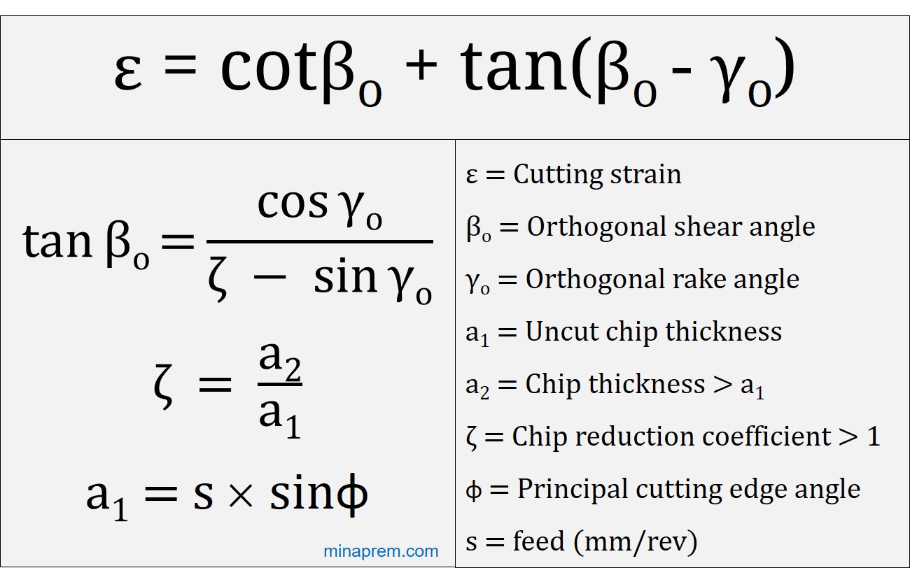
\[\varepsilon = \cot {\beta _o} + \tan ({\beta _o} – {\gamma _o})\]
As given in the question, the cutting tool has zero orthogonal rake angle (γO). However, the value of shear angle (βO) is not provided in the question. This shear angle indicates the inclination of the shear plane with respect to the cutting velocity vector. Once again, for orthogonal machining with a sharp tool, the shear angle can be expressed in terms of orthogonal rake angle (γO) and chip reduction coefficient (ζ), as displayed below.
\[\tan {\beta _O} = \frac{{\cos {\gamma _O}}}{{\zeta – \sin {\gamma _O}}}\]
The chip reduction coefficient (ζ), commonly called by its acronym as CRC, is one crucial parameter that indicates the increment of chip thickness during machining. Primarily due to shear stain, the thickness of the chip increases as compared to that exists before shearing. This chip thickness becomes larger than uncut chip thickness, particularly for conventional macro scale machining. The ratio between the chip thickness (a2) to the uncut chip thickness (a1) is termed as chip reduction coefficient (ζ).
\[{\bf{\zeta }} = \frac{{{a_2}}}{{{a_1}}} > 1\]
The chip thickness (a2) is directly provided in the question. However, the uncut chip thickness (a1) is not given, rather the feed rate is given. In case of orthogonal straight turning operation, the uncut chip thickness can be obtained from the feed (s) and principal cutting edge angle (φ) of the tool. Note that in case of turning the uncut chip thickness (a1) is independent of depth of cut that is normally given in machine transverse direction. The value of a1 relies only on s and φ as displayed below.
\[{a_1} = s.\sin \phi \]
Another clue that is given in question is that the machining operation is orthogonal turning of a hollow cylindrical pipe. This is the situation of pure orthogonal turning where tool nose is suppose to have no contact with the workpiece—only a certain length of the principal cutting edge will engage with wall of the hollow cylindrical pipe. The wall thickness is also comparatively smaller than the length of principal cutting edge. The tool should also have 90° principal cutting edge angle (φ) and preferably 0° inclination angle. Therefore, φ = 90° is given.
Step-1: Calculate chip reduction coefficient (ζ)
Principal cutting edge angle (φ) = 90°
Feed (s) = 0.2mm/rev
∴ Uncut chip thickness (a1) = s´sinφ = 0.2´sin90 = 0.2mm
Chip thickness (a2) = 0.5mm
∴ Chip reduction coefficient (ζ) = 0.5/0.2 = 2.5
Step-2: Calculate shear angle (βO)
Given, orthogonal rake angle (γO) = 0°
or, \(\tan {\beta _O} = \frac{{\cos 0}}{{2.5 – \sin 0}} = 0.4\)
or, \({\beta _O} = {\tan ^{ – 1}}0.4 = 21.8\)
Step-3: Calculate shear strain (ε)
\(\varepsilon = \cot {\beta _o} + \tan ({\beta _o} – {\gamma _o})\)
or, \(\varepsilon = \cot 21.8 + \tan (21.8 – 0)\)
or, \(\varepsilon = 2.9\)
Therefore, shear strain for the given case is 2.9. It is one unitless quality as strain is the ratio of two lengths.