Question: An orthogonal turning operation is carried out at 20m/min cutting speed, using a cutting tool of rake angle 15°. The chip thickness is 0.4mm and the uncut chip thickness is 0.2mm. Determine (i) the shear plane angle in degrees, and (ii) the chip velocity in m/min. [GATE 2009]
Answer: In conventional machining the workpiece material is removed by shearing as and when the cutting tool compresses it. For simplicity in analysis, it is assumed that sharing takes place in a concentrated 2-D plane. This plane is termed as shear plane. Angle of inclination of this shear plane from the cutting velocity vector is called shear plane angle (βO). This shear plane angle can be expressed in terms of chip reduction coefficient (ζ) and orthogonal rake angle (γO) of the cutting tool, as given below.
\[\tan {\beta _O} = \frac{{\cos {\gamma _O}}}{{\zeta – \sin {\gamma _O}}}\]
The Chip Reduction Coefficient (ζ) is the ratio between the chip thickness (a2) to the uncut chip thickness (a1). So it is one unitless quantity. The chip thickness is usually larger than the corresponding uncut chip thickness (i.e. a2 > a1) because of the positive shear strain that exists in machining. Thus Chip Reduction Coefficient is always greater than one, particularly in macro-scale machining. Mathematically,
\[\zeta = \frac{{{a_2}}}{{{a_1}}} > 1\]
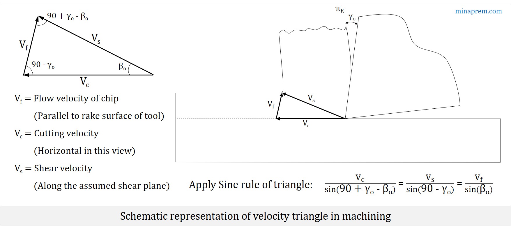
In an orthogonal machining of ductile material with a sharp cutting tool, three velocity parameters namely cutting velocity (VC), chip flow velocity (Vf) and shear velocity (VS) together constitute a triangle, as shown below. Since the shear velocity is oriented along the assumed shear plane, the angle between cutting velocity (VC) and shear velocity (VS) is nothing but the shear angle (βO). The chip flow velocity (Vf) is considered along the rake surface and thus its angle with the reference plane is equal to the orthogonal rake angle (γO). Thus, angle between cutting velocity (VC) and chip flow velocity (Vf) is (90° – γO). Once two angles of a triangle is known, the third angle can be obtained easily as the sum of all three internal angles of any triangle is 180°. Therefore, application of Sine Rule on the velocity triangle gives the following expression.
\[\frac{{{V_c}}}{{\sin \left( {90 + {\gamma _o} – {\beta _o}} \right)}} = \frac{{{V_s}}}{{\sin \left( {90 – {\gamma _o}} \right)}} = \frac{{{V_f}}}{{\sin {\beta _o}}}\]
Part-1: Calculate shear plane angle
Given, orthogonal rake angle (γO) = +15°
Chip thickness (a2) = 0.4mm
Uncut chip thickness (a1) = 0.2mm
∴ Chip Reduction Coefficient (ζ) = (a2 / a1) = (0.4 / 0.2) = 2.0
Substituting these values, the shear plane angle can be calculated as follows.
\[\tan {\beta _O} = \frac{{\cos 15}}{{2 – \sin 15}} = 0.554\]
\[{\beta _O} = {\tan ^{ – 1}}\left( {0.554} \right) = 29\]
Therefore, shear plane angle for the given case is 29°.
Part-2: Calculate chip velocity
Here, the cutting velocity (VC) is given as 20m/min and the requirement is chip flow velocity (Vf). Both the orthogonal rake angle (γO) and the shear plane angle (βO) are known. Thus, extracting the VC and Vf terms from the generalised expression obtained from velocity triangle, the following can be written. Further substituting the values of corresponding parameters, the chip velocity can be obtained.
\[\frac{{{V_c}}}{{\sin \left( {90 + {\gamma _o} – {\beta _o}} \right)}} = \frac{{{V_f}}}{{\sin {\beta _o}}}\]
\[\frac{{20}}{{\sin \left( {90 + 15 – 29} \right)}} = \frac{{{V_f}}}{{\sin 29}}\]
\[{V_f} = \frac{{20\sin 29}}{{\sin 76}}\]
\[{V_f} = 10\]
Therefore, chip velocity for the given case is 10 m/min.