GATE

Calculate coefficient of friction from cutting and thrust force for zero rake

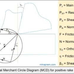
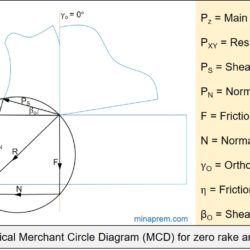
Question: In an orthogonal cutting process the tool used has rake angle of zero degree. The measured cutting force and thrust force are 500 N and 250 N, respectively. What is the coefficient of friction between the tool and the chip? [GATE 2016] Solution: This problem can be solved with the help of Merchant Circle Diagram (MCD). MCD is the graphical representation of various forces associated with an orthogonal machining

Calculate power consumption from coefficient of friction and thrust force

Question: A single point cutting tool with 0° rake angle is used in an orthogonal machining process. At a cutting speed of 180 m/min, the resultant thrust force is 490 N. If the coefficient of friction between the tool and the chip is 0.7, then calculate the power consumption for the machining operation. [GATE 2015] Solution: Cutting power consumption in orthogonal machining can be estimated from main cutting force (PZ),

Determine rake angle and normal force if main cutting force is perpendicular to friction force

Question: In orthogonal turning of a bar of 100 mm diameter with a feed of 0.25 mm/rev, depth of cut of 4 mm and cutting velocity of 90 m/min, it is observed that the main (tangential) cutting force is perpendicular to friction force acting at the chip‐tool interface. The main (tangential) cutting force is 1500 N. (i) Determine the orthogonal rake angle of the cutting tool. (ii) Determine the normal

Typical Merchant Circle Diagram (MCD) for positive rake angle

Question: The Merchant circle diagram showing various forces associated with a cutting process using a wedge-shaped tool is given in the adjacent Figure. The coefficient of friction can be estimated from the ratio: [GATE 2017] (i) f1 / f2 (ii) f3 / f4 (iii) f5 / f6 (iv) f6 / f5 Solution: Merchant Circle Diagram (MCD) is the graphical representation of various forces associated with an orthogonal machining operation. It

Typical Merchant Circle Diagram (MCD) for zero rake angle

Question: In orthogonal turning of an engineering alloy, it has been observed that the friction force acting at the chip-tool interface is 402.5 N and the friction force is also perpendicular to the cutting velocity vector. The feed velocity is negligibly small with respect to the cutting velocity. The ratio of friction force to normal force associated with the chip‐tool interface is 1. The uncut chip thickness is 0.2 mm

Schematic representation of shear strain and shear strain rate in machining

Question: Details pertaining to an orthogonal metal cutting process are given below. Chip thickness ratio = 0.4 Undeformed thickness = 0.6 mm Rake angle = +10° Cutting speed = 2.5 m/s Mean thickness of primary shear zone 25 microns. Determine shear strain rate in s–1 during the process. [GATE 2012] Solution: During machining, as the cutting tool compresses a layer of material, it gets sheared off in the form of

Determine shear plane angle and chip velocity in orthogonal turning

Question: An orthogonal turning operation is carried out at 20m/min cutting speed, using a cutting tool of rake angle 15°. The chip thickness is 0.4mm and the uncut chip thickness is 0.2mm. Determine (i) the shear plane angle in degrees, and (ii) the chip velocity in m/min. [GATE 2009] Answer: In conventional machining the workpiece material is removed by shearing as and when the cutting tool compresses it. For simplicity

Tool rake angle conversion from ORS to ASA – calculate PCEA

Question: In a single point turning tool, the side rake angle and orthogonal rake angle are equal. φ is the principal cutting edge angle and its range is 0° ≤φ≤ 90°. The chip flows in the orthogonal plane. Determine the value of φ. [GATE 2008] Answer: Although in majority of the analysis for straight turning, it is assumed that the chip is flowing in orthogonal direction, but actually chip flow

Shear strain from feed, chip thickness and rake angle

Question: During orthogonal turning operation of a hollow cylindrical pipe, it is found that the thickness of the chip produced is 0.5mm. The feed given to the zero degree rake angle tool is 0.2mm/rev. Calculate the shear strain produced during the operation? [GATE 2014] Solution: Cutting stain indicates the shear strain developed during any conventional machining operation due to the shearing of one thin layer of workpiece material over another

Schematic representation of chip reduction coefficient and shear angle

Question: In an orthogonal machining with a tool of 9° orthogonal rake angle, the uncut chip thickness is 0.2mm. The chip thickness fluctuates between 0.25mm and 0.4mm. Determine the ratio between the maximum shear angle to the minimum shear angle in this case. [GATE 2017] Solution: Machining is one subtractive manufacturing process where material is gradually removed from the workpiece by shearing under the presence of compressive force exerted by