Question: In an orthogonal machining with a tool of 9° orthogonal rake angle, the uncut chip thickness is 0.2mm. The chip thickness fluctuates between 0.25mm and 0.4mm. Determine the ratio between the maximum shear angle to the minimum shear angle in this case. [GATE 2017]
Solution: Machining is one subtractive manufacturing process where material is gradually removed from the workpiece by shearing under the presence of compressive force exerted by the cutting tool. The assumed plane along which shearing takes place is called shear plane. Inclination of this shear plane with respect to cutting velocity vector is called shear angle. This orthogonal shear angle (βo) can be expressed in terms of orthogonal rake angle (γo) and chip reduction coefficient (ζ), as displayed below.
\[\tan {\beta _O} = \frac{{\cos {\gamma _O}}}{{\zeta – \sin {\gamma _O}}}\]
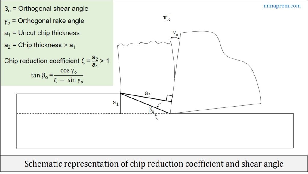
Rake angle of the cutting tool comes under tool geometry and can be categorised as an independent variable once a specific tool is selected for machining. However, chip reduction coefficient (ζ) is a variable and depends on several properties. By definition, chip reduction coefficient is the ratio between the chip thickness (a2) and the uncut chip thickness (a1). In conventional macro-scale cutting, chip thickness is always larger than uncut chip thickness (i.e. a2 > a1) because of lamellar shearing and straining. Mathematically,
ζ = (a2 / a1) > 1
In this particular case uncut chip thickness (a1) is given as 0.2mm and the orthogonal rake angle (γo) is given as +9°. Therefore, from the general expression of shear angle (βo), given at beginning, it can be said that βo is inversely proportional to ζ. Further, βo is also inversely proportional to a2.
\({\beta _O} \propto \frac{1}{\zeta }\) [As, 0° < γo < 90°; 0° < βo < 90°]
\({\beta _O} \propto \frac{1}{{{a_2}}}\) [∵ ζ = a2 / a1]
Determine maximum shear angle
Since shear angle is inversely proportional to the chip thickness, so maximum shear angle can be obtained for minimum value of chip thickness for a constant uncut chip thickness. This in this particular case as given in question, maximum shear angle will be correspond to the 0.25mm chip thickness. So for γo = 9°, a1 = 0.2mm and a2 = 0.25mm, let us calculate maximum shear angle.
\[\tan {\beta _{O,\max }} = \frac{{\cos 12}}{{\left( {\frac{{0.25}}{{0.2}} – \sin 12} \right)}} = 0.938\]
\[{\beta _{O,\max }} = {\tan ^{ – 1}}\left( {0.938} \right) = 43.19\]
Determine minimum shear angle
Opposite to the maximum shear angle, the minimum shear angle will be obtained for maximum value of chip thickness. Here the maximum chip thickness is given as 0.4mm. Therefore, for γo = 9°, a1 = 0.2mm and a2 = 0.40mm, let us calculate minimum shear angle.
\[\tan {\beta _{O,\min }} = \frac{{\cos 12}}{{\left( {\frac{{0.4}}{{0.2}} – \sin 12} \right)}} = 0.546\]
\[{\beta _{O,\min }} = {\tan ^{ – 1}}\left( {0.546} \right) = 28.63\]
Determine ratio between maximum and minimum shear angle
For the given case, the maximum and minimum shear angle are determined above. As asked in the question, the ratio between them can also be calculated easily.
\[\frac{{{\beta _{O,\max }}}}{{{\beta _{O,\min }}}} = \frac{{43.19}}{{28.63}} = 1.5\]