Question: Details pertaining to an orthogonal metal cutting process are given below.
- Chip thickness ratio = 0.4
- Undeformed thickness = 0.6 mm
- Rake angle = +10°
- Cutting speed = 2.5 m/s
Mean thickness of primary shear zone 25 microns. Determine shear strain rate in s–1 during the process. [GATE 2012]
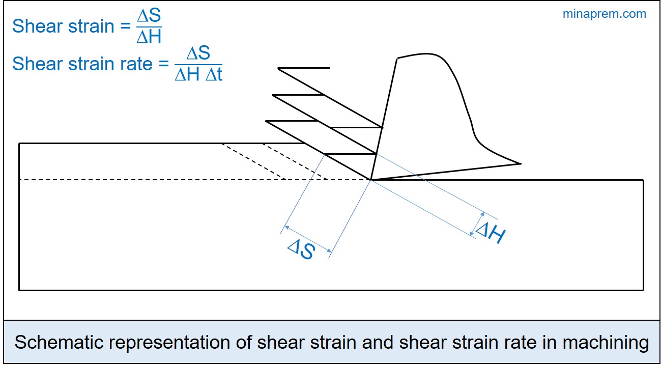
Solution: During machining, as the cutting tool compresses a layer of material, it gets sheared off in the form of chips. The strain produces during chip formation is called cutting strain. The rate of this shear strain can be obtained by dividing cutting strain with straining time. As shown in the schematic diagram below, the shear deformation is indicated by ΔS, the original thickness of shear plane is indicated by ΔH and the shearing time is indicated by Δt. Now, the ratio between ΔS and Δt indicates the shear velocity (VS). Therefore, the shear strain rate can be expressed as follows.
Shear strain rate = \(\frac{{\Delta S}}{{\Delta H\Delta t}} = \frac{1}{{\Delta H}}\left( {\frac{{\Delta S}}{{\Delta t}}} \right) = \frac{{{V_S}}}{{\Delta H}}\)
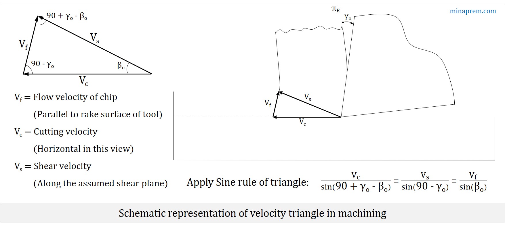
However, the shear velocity (VS) is one unknown quantity here. Velocity triangle in machining provides a relation between cutting velocity (VC), chip flow velocity (Vf) and shear velocity (VS) in terms of orthogonal rake angle (γO) of the cutting tool and shear plane angle (βO). As shown in the diagram below, the generalised expression obtained from velocity triangle by applying sine rule can be expressed as follows.
\[\frac{{{V_c}}}{{\sin \left( {90 + {\gamma _o} – {\beta _o}} \right)}} = \frac{{{V_s}}}{{\sin \left( {90 – {\gamma _o}} \right)}} = \frac{{{V_f}}}{{\sin {\beta _o}}}\]
Since cutting velocity (VC) is given, so shear velocity (VS) can be calculated from the relevant parts of the above generalized expression. The only unknown quantity is the shear angle (βO). For an orthogonal machining, the shear angle can be expressed in terms of chip reduction coefficient (ζ) and orthogonal rake angle (γO) of the cutting tool, as provided below. Since all required parameters are known, so the problem can now be solved.
\[\tan {\beta _O} = \frac{{\cos {\gamma _O}}}{{\zeta – \sin {\gamma _O}}}\]
Step-1: Calculate shear plane angle (βO)
Given, orthogonal rake angle (γO) = +10°
Chip thickness ratio (rc) = 0.4
∴ Chip reduction coefficient (ζ) = 1/rc = 1/0.4 = 2.5
\[\tan {\beta _O} = \frac{{\cos {\gamma _O}}}{{\zeta – \sin {\gamma _O}}} = \frac{{\cos 10}}{{2.5 – \sin 10}} = 0.4233\]
\[{\beta _O} = {\tan ^{ – 1}}\left( {0.4233} \right) = 22.94\]
Step-2: Calculate shear velocity (VS)
Given, cutting velocity (VC) = 2.5 m/s
From generalised expression for velocity triangle, the following intended part can be written:
\[\frac{{{V_c}}}{{\sin \left( {90 + {\gamma _o} – {\beta _o}} \right)}} = \frac{{{V_s}}}{{\sin \left( {90 – {\gamma _o}} \right)}}\]
\[\frac{{{V_c}}}{{\cos \left( {{\beta _o} – {\gamma _o}} \right)}} = \frac{{{V_s}}}{{\cos \left( {{\gamma _o}} \right)}}\]
\[\frac{{2.5}}{{\cos \left( {22.9 – 10} \right)}} = \frac{{{V_s}}}{{\cos \left( {10} \right)}}\]
\[{V_S} = \frac{{2.5\cos \left( {10} \right)}}{{\cos \left( {12.9} \right)}} = 2.526\]
Step-3: Calculate shear strain rate
Given, mean thickness of primary shear zone (ΔH) = 25 microns
So the shear strain rate can be calculated as follows:
\[\mathop \varepsilon \limits^. = \frac{{{V_S}}}{{\Delta H}} = \frac{{2.526}}{{25 \times {{10}^{ – 6}}}} = 1.01 \times {10^{ + 5}}\]
Therefore, shear strain rate for the given case is 1.01×10⁵ s-1.