Chips generated during machining flow over the rake surface of the cutting tool before it leaves the machining zone. Intense rubbing under high contact pressure between flowing chip and rake surface leads to excessive heat generation. The contact region also gives rise to secondary deformation zone that contributes over 70% of the total cutting heat. Although majority of the cutting heat generated in secondary deformation zone flows away with the moving chip, substantial amount of heat also diffuses into the cutting tool.
Excessive heat on cutting tool leads to several undesired effects including accelerated wear and lower tool life. High cutting temperature normally degrades overall machinability. Thus reduction of cutting temperature is indispensably necessary. One effective way to fulfil this requirement is to reduce the friction at tool‐chip interface so that rate of heat generation at the secondary deformation zone can be reduced. Below are few feasible ways to reduce the friction at tool‐chip interface.
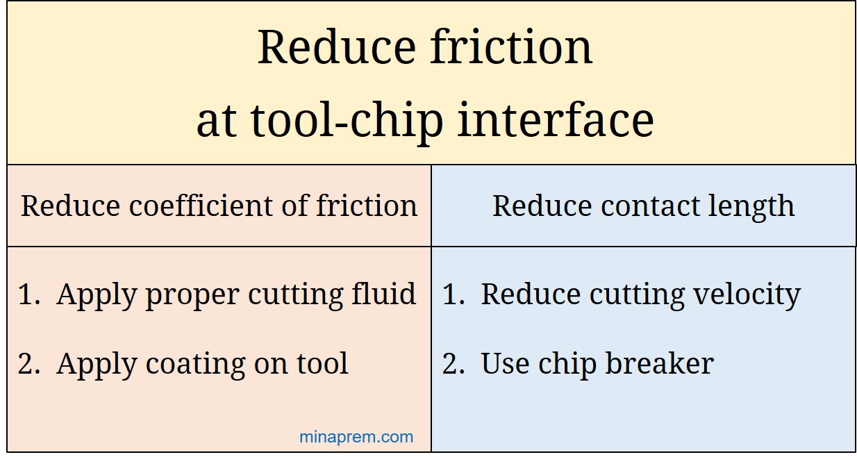
- Applying proper cutting fluid
- Applying appropriate coating on cutting tool
- Reducing cutting velocity
- Making step or groove on rake surface
Application of cutting fluid: Cutting fluids serve two different roles in machining—lubrication and cooling. The lubrication effect acts prior to heat generation, whereas the cooling effect acts after heat generation. Lubricity of the cutting fluid is helpful in reducing friction at the tool‐chip interface because the fluid, if selected properly, can descend the dynamic coefficient of friction between the flowing chip and rake face of the tool. However, problem arises due to immense contact pressure between chip and rake face as the fluid fails to penetrate properly into the contact region. Thus fluid delivery technique is equally important to achieve proper lubricating effect. Attention should also be given in selection of cutting fluid for achieving perceptible lubrication effect for a given workpiece-tool material combination.
Coated cutting tool: Another way to descend coefficient of friction between the chip and rake face is by applying appropriate coating layer on the cutting tool. Coated tools offer numerous benefits like low wear rate, extended tool life, high shape retention capability, etc. Now-a-days multi-layer coating (each layer thickness around 5μm) is gaining popularity where each layer is targeted towards one objective. For example, the top most layer might be focusing on reduction of coefficient of friction, the second layer can be for reflection of heat (to reduce heat influx to the cutting tool), the third layer might be for lessening of atomic diffusion rate, the fourth layer might be for improving toughness, and so on. Sometimes one single layer can fulfil multiple objectives. Thus an appropriate coating layer on cutting tool can substantially decline the friction between the chip and rake face.
Low cutting velocity: The entire contact length (CN) between the chip and rake surface comprises two distinct parts. Towards the tip there exists a plastic zone of length CP and after that there exists an elastic zone of length CE (i.e. CN = CP + CE). The cutting fluid can easily penetrate into the elastic zone by capillary action; however, fails to penetrate into the plastic zone. Thus lubrication effect can be achieved within this elastic zone only. With increase in cutting velocity, the length of plastic zone increases even though the overall contact length remains same. Thus in high speed machining the length of elastic zone (CE) shrinks, whereas the length of plastic zone (CP) increases. Accordingly, friction increases with cutting velocity as the lubricity of cutting fluid is primarily based on elastic zone. It is worth that the kinetic coefficient of friction is independent of relative velocities between two solid objects under contact.
Step or groove on rake surface: Another external way of reducing contact length between chip and rake surface is my making a groove or step on the rake surface at an optimum distance from the cutting edges. Primary aim for such groove or step is to break the chip repeatedly (i.e. as chip breaker), and thus to avoid risks associated with long continuous chips. Such groove or step on the rake surface also help in reducing the contact length and thereby reduces friction at chip-tool interface.