Question: In orthogonal turning of an engineering alloy, it has been observed that the friction force acting at the chip-tool interface is 402.5 N and the friction force is also perpendicular to the cutting velocity vector. The feed velocity is negligibly small with respect to the cutting velocity. The ratio of friction force to normal force associated with the chip‐tool interface is 1. The uncut chip thickness is 0.2 mm and the chip thickness is 0.4 mm. The cutting velocity is 2 m/s.
(i) Calculate the shear force acting along the primary shear plane.
(ii) Assume that the energy expended during machining is completely converted to heat. What will be the rate of heat generation at the primary shear plane? [GATE 2010]
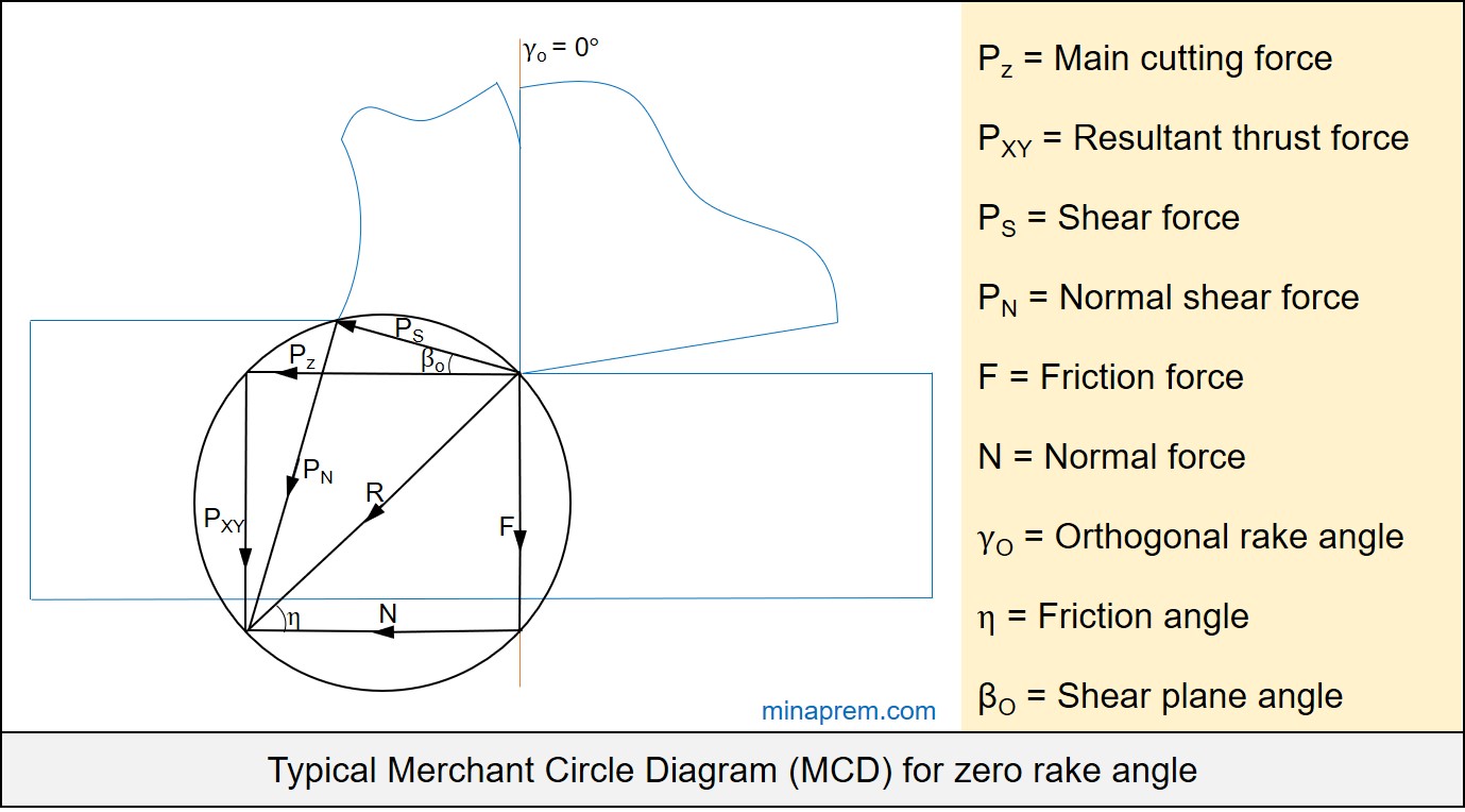
Solution: To solve this question, we need to take help of Merchant Circle Diagram (MCD). MCD is one graphical representation of several forces that act during orthogonal machining with a sharp cutting tool. One condition given here is that the friction force (F) is perpendicular to the cutting velocity vector (VC). This is possible only if the orthogonal rake angle of the cutting tool is zero (i.e. γO = 0°). In such case, main cutting force (PZ) will be parallel to normal force (N) and also the resultant thrust force (PXY) will be parallel to the friction force (F). Therefore, PZ, PXY, N and F together constitute a rectangle. Such a Merchant Circle Diagram is displayed below.
Following values are given in question
Friction force (F) = 402.5 N
Orthogonal rake angle (γO) = 0° [Because friction force is perpendicular to cutting velocity vector]
Feed velocity is negligible
Friction force / Normal force = F / N = 1
Uncut chip thickness (a1) = 0.2 mm
Chip thickness (a2) = 0.4 mm
Cutting velocity (VC) = 2 m/s
Step-1: Calculate friction angle (η)
Consider the triangle made by R, F and N. Since R is the diameter of the circle, so it has to be one right angle triangle where the angle between N and F is 90°. Since the smaller angle between R and N is equal to friction angle (η), so the following can be written.
\[\tan \eta = \frac{F}{N}\]
However, F / N = 1, as given in question. Therefore,
\[\tan \eta = 1 = \tan 45\]
\[\eta = 45^\circ \]
Step-2: Calculate shear plane angle (βO)
In orthogonal cutting, shear plane angle (βO) can be calculated using chip reduction coefficient (ζ) and orthogonal rake angle (γO). Here orthogonal rake angle is zero. The chip reduction coefficient (ζ) is the ratio between chip thickness to the uncut chip thickness. Since there values ae known, so it can be calculated as follows.
\[\zeta = \frac{{{a_2}}}{{{a_1}}} = \frac{{0.4}}{{0.2}} = 2\]
Therefore, the shear plane angle be:
\[\tan {\beta _O} = \frac{{\cos {\gamma _O}}}{{\zeta – \sin {\gamma _O}}}\]
\[\tan {\beta _O} = \frac{{\cos 0}}{{2 – \sin 0}} = \frac{1}{2} = 0.5\]
\[{\beta _O} = {\tan ^{ – 1}}\left( {0.5} \right) = 26.56^\circ \]
Step-3: Calculate the shear force (PS)
The only one known force in this case is the friction force (F). However, all three relevant angles are known. So any other force can be calculated easily. Let us consider the right angle triangle made by F, N and R. The F value is given as 402.5 N. So let us calculate R first.
\[\sin \eta = \frac{F}{R}\]
\[R = \frac{F}{{\sin \eta }} = \frac{{402.5}}{{\sin 45}} = 569.22\]
Now once again consider the right angle triangle made by PS, PN and R. The angle between PS and R is equal to (βO + η). Therefore, from the known value of R, the intended PS value can be calculated easily as shown below.
\[\cos \left( {{\beta _O} + \eta } \right) = \frac{{{P_S}}}{R}\]
\[{P_S} = R \times \cos \left( {{\beta _O} + \eta } \right)\]
\[{P_S} = 569.22 \times \cos \left( {26.56 + 45} \right)\]
\[{P_S} = 180.05\]
Therefore, the shear force acting along the primary shear plane (PS) is 180.05 N.
Step-4: Calculate rate of heat generation at primary shear plane
There exist two primary sources for heat generation in machining – (i) the chip-tool interface and (ii) primary shear plane. Assuming that the energy expended during machining is completely converted to heat, the approximate rate of heat generation in these two zones can be obtained simply by multiplying the corresponding force and velocity. That means:
- Rate of heat generation at chip-tool interface = F Vf
- Rate of heat generation at primary shear plane = PS VS
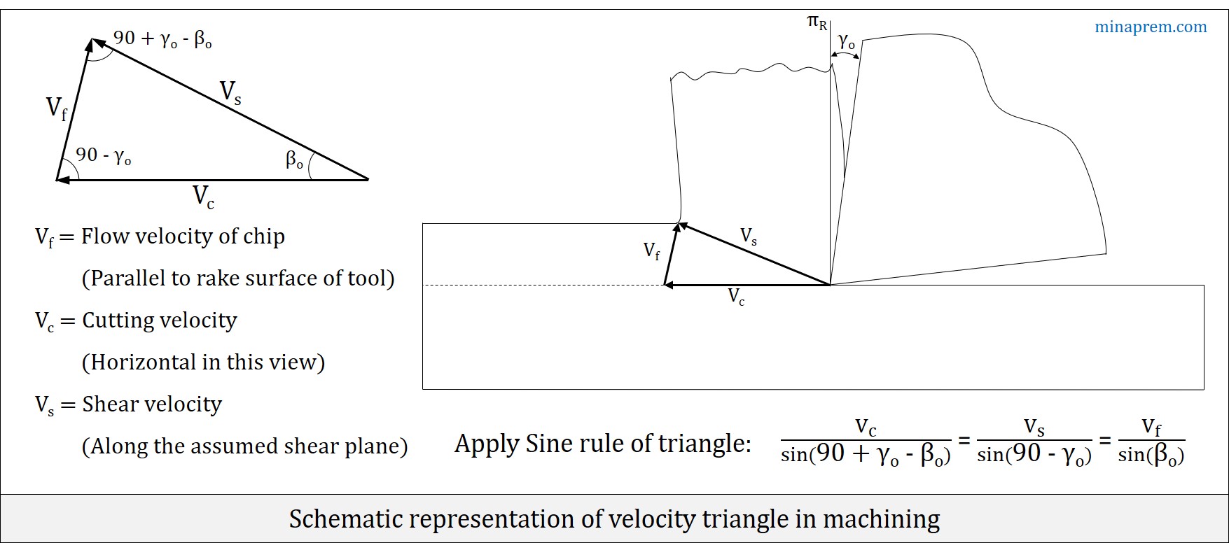
In order to calculate the rate of heat generation at primary shear plane, we need the shear velocity (VS). However, the cutting velocity (VC) is provided in question. For orthogonal cutting, the velocity triangle gives the relation between three velocity terms – cutting velocity (VC), shear velocity (VS) and chip flow velocity (Vf), as schematically shown in the generalised diagram below. In this case the orthogonal rake angle (γO) is zero, thus the velocity triangle will also be a right angle triangle (angle between VC and Vf will be 90°). Sine relevant angles are known, so shear velocity (VS) can be calculated from known value of cutting velocity (VC), as illustrated below.
\[\frac{{{V_c}}}{{\sin \left( {90 + {\gamma _o} – {\beta _o}} \right)}} = \frac{{{V_s}}}{{\sin \left( {90 – {\gamma _o}} \right)}}\]
\[\frac{2}{{\sin \left( {90 + 0 – 26.56} \right)}} = \frac{{{V_s}}}{{\sin \left( {90 – 0} \right)}}\]
\[{V_s} = \frac{{2 \times \sin 90}}{{\cos 26.56}} = 2.236\]
Therefore, shear velocity (PS) for the given case is 2.236 m/s. Hence the rate of heat generation at shear zone can be calculated as follows:
Rate of heat generation at primary shear plane = PS VS
∴ Rate of heat generation at primary shear plane = 180.05 × 2.236 = 403.6 W