In orthogonal machining, cutting velocity (VC) , chip flow velocity (Vf) and shear velocity (VS) are interrelated. These three velocity vectors together form a triangle, which is called velocity triangle in machining. A typical velocity triangle is depicted below. Here length of the sides of the triangle indicates the magnitude of corresponding velocity. The triangle is based on the assumptions of orthogonal machining (chip is flowing in orthogonal direction) and single shear plane (indicates shearing is occurring in a concentrated 2-D shear plane rather than through a region). It is worth mentioning that the velocity triangle need not necessarily be one right angle triangle under all circumstances; it will occur only in specific cases.
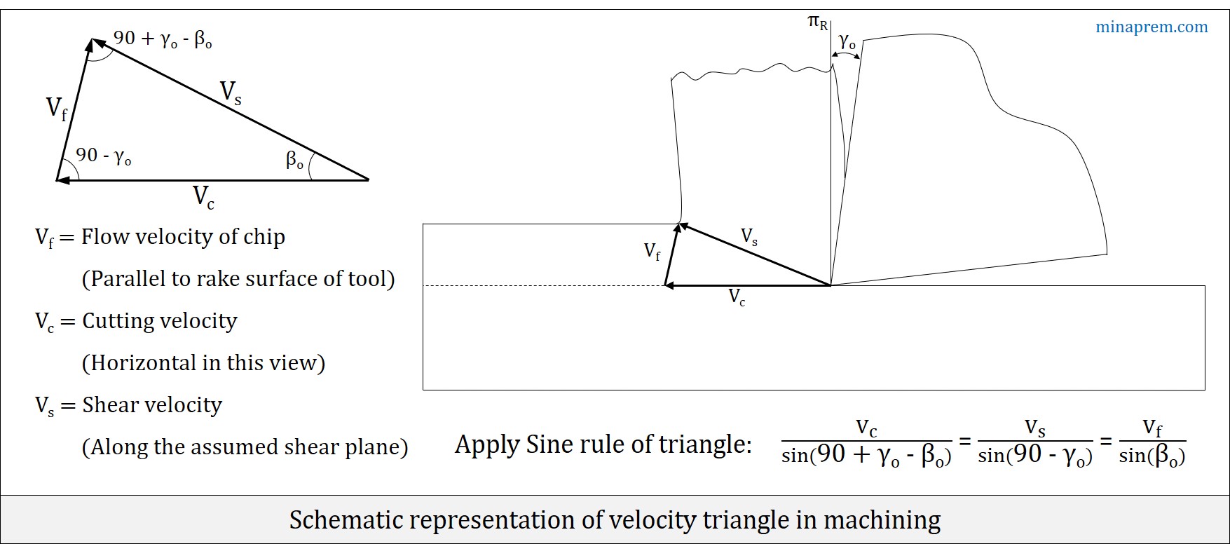
The chip flow velocity (Vf) vector should be parallel to the rake surface of the cutting tool. Since cutting velocity (VC) vector is always horizontal in the view as shown above, so the angle between the VC and Vf depends on orthogonal rake angle (γO) of the cutting tool. In fact, the angle between VC and Vf will be (90° – γO). Since γO can be either negative, zero or positive, so algebraic sum is required to consider.
By definition, shear angle (βO) is the angle of orientation of the assumed shear plane from the cutting velocity (VC) vector, as measured on orthogonal plane (πO). Again, the shear velocity (VS) vector is drawn along the assumed shear plane. Thus, angle between cutting velocity (VC) vector and shear velocity (VS) vector will be equal to orthogonal shear angle (βO).
When two angles of a triangle are known, the third angle can be easily calculated because sum of all three angels of any triangle is 180°. Therefore, angle between shear velocity (VS) vector and chip velocity (Vf) vector be [180 – (90° – γO) – βO] = (90° + γO – βO).
Since all three angles of the triangle is known, so Sine Rule can be applied. Law of sine states that, for an arbitrary triangle, the ratio between the length of a particular cord and the sine of its opposite angle is a constant. Hence, for this particular velocity triangle, the following equation can be written. This equation is very important in mechanics of machining as it provides an interrelation between cutting velocity, chip velocity and shear velocity.
\[\frac{{{V_c}}}{{\sin \left( {90 + {\gamma _o} – {\beta _o}} \right)}} = \frac{{{V_s}}}{{\sin \left( {90 – {\gamma _o}} \right)}} = \frac{{{V_f}}}{{\sin {\beta _o}}}\]
When velocity triangle will be a right angle triangle? There is absolutely no guarantee that the velocity triangle will be a right angle triangle under all circumstances. It is possible in two specific cases only. Case-1: when orthogonal rake angle (γO) of the cutting tool is zero. In this situation, angle between cutting velocity (VC) vector and chip flow velocity (Vf) vector will be 90°. Case-2: when the orthogonal shear angle (βO) becomes same with orthogonal rake angle (γO). In this situation, angle between shear velocity (VS) vector and chip velocity (Vf) vector will be 90°. If case-1 occurs then case-2 will not occur (because, 0° < βO ≤ 45°), and vice versa. Irrespective of the scenario, the general formula obtained by sine rule is always valid.