Cutting tools are usually provided with a pre-defined nose radius. Presence of nose radius makes the tool tip stronger and thus tool becomes capable of withstanding larger cutting force without failure. To some extent it contributes in smoothening machined surface (thus reduces surface roughness). However, for the sake of estimating surface roughness in machining, when tool nose radius is very small as compared to depth of cut, it is considered as a sharp tool. Alternatively, when nose radius is significant as compared to depth of cut, the former one becomes predominant in influencing surface roughness. Gradual wear can also convert a sharp tool to blunt one.
As usual surface finish cannot be determined quantitatively. It is the surface roughness which is required to determine and its value can be used to judge level of surface finish. In fact, they are inversely proportional. So high surface roughness indicates poor surface finish and vice versa. Surface roughness in straight turning using a single point cutting tool with rounded tip can be estimated as discussed in the subsequent sections.
Estimation of surface roughness in turning using a rounded tool
Schematic diagram of external straight turning operation using a right handed single point turning tool having nose radius r is shown below. The cylindrical workpiece, mounted in a three jaw chuck, is rotated at a constant speed of N rpm (revolution per minute), while the cutting tool is fed against the workpiece at a constant feed rate of s mm/rev. Here it is assumed that the give depth of cut is higher than the nose radius of the tool but nose radius is also considerable (not negligible).
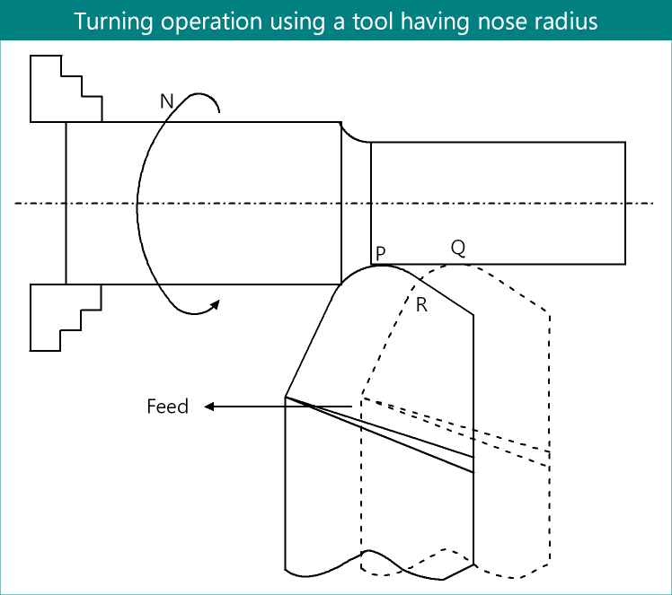
Above figure also shows the positions of cutting tool in two successive revolutions. Thus the distance PQ is equals to the feed rate per revolution, designated by s. A close consideration will reveal that the area enclosed by PQR will not be removed; instead it will remain attached with the finished surface of the job leading to surface roughness. This area PQR will replicate throughout the entire circumference of the job in every revolution. Therefore, the maximum surface roughness will be the distance between finished surface and point R, which is required to determine.
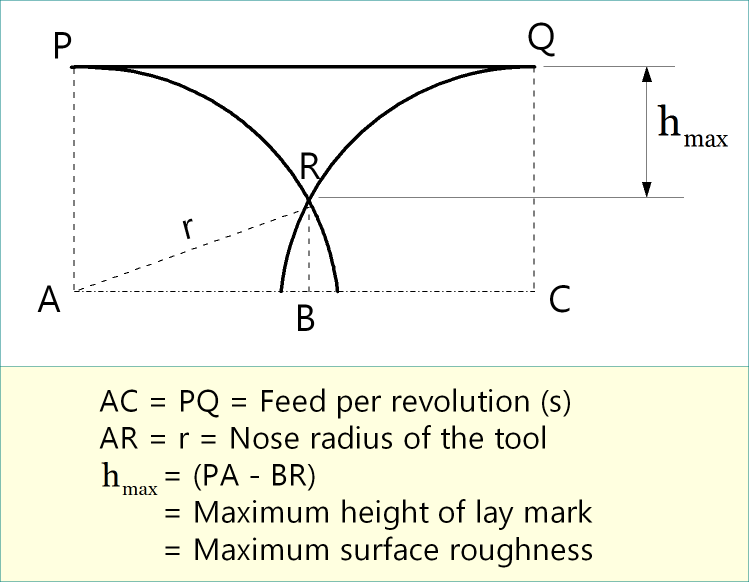
A magnified view of the area PQR is depicted below. Note that nose radius (or QC or AP) does not necessarily equal to depth of cut (t); in fact t is usually larger than AP (to avoid high chip deviation from orthogonal plane via restricted cutting effect). In practice, surface roughness parameter (hmax) is very small as compared to feed rate or nose radius of the tool. The following passages elaborate steps to determine hmax.
Mathematical derivation of formula
From ΔABR, (AR)2 = (AB)2 + (BR)2
or, \(A{R^2} = {\left( {{{PQ} \over 2}} \right)^2} + {\left( {AP – {h_{\max }}} \right)^2}\)
or, \({r^2} = {\left( {{s \over 2}} \right)^2} + {\left( {r – {h_{\max }}} \right)^2}\)
or, \({r^2} = {{{s^2}} \over 4} + {r^2} – 2r{h_{\max }} + {\left( {{h_{\max }}} \right)^2}\)
or, \(0 = {{{s^2}} \over 4} – 2r{h_{\max }} + {\left( {{h_{\max }}} \right)^2}\)
or, \(0 = {{{s^2}} \over 4} – 2r{h_{\max }}\) [Neglecting smaller term]
or, \(2r{h_{\max }} = {{{s^2}} \over 4}\)
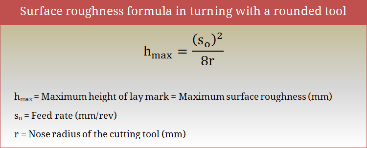
or, \({h_{\max }} = {{{s^2}} \over {8r}}\)
References
- Book: Advances in Manufacturing Technology XV by D. T. Pham, S. S. Dimov and T. O’Hagan (Professional Engineering Publishing Limited).
- Proceedings: K. S. Umashankar, B. J. Manujesh and N. A. Jnanesh; Recurrence Qualification Analysis – A Tool to Analyze the Surface Finish During Machining; Advances in Mechanical Engineering; 2010.
- Book: Machining and Machine Tools by A. B. Chattopadhyay (Wiley).
- Book: Metal Cutting: Theory And Practice by A. Bhattacharya (New Central Book Agency).