A cutting tool can never be perfectly sharp! Theoretical limit of minimum radius is equal to radius of atom of tool material. Conventional turning tools (SPTT) usually have nose radius between 0.4 – 1.2mm. However, for estimation of surface roughness, effects of nose radius of the tool (r) can be neglected when it is considerably lower than depth of cut (t). Such tools can be safely considered as a sharp one. While turning using such cutting tools, surface roughness can be estimated with the help of feed rate and few tool angles as discussed below.
Derivation of surface roughness formula in turning with a sharp tool
Schematic diagram of external straight turning operation in a conventional lathe is depicted below. The cylindrical work piece is mounted in a three-jaw chuck and it is rotated at a constant speed of N rpm (revolution per minute). A sharp single point right handed cutting tool is used to remove excess layer of material. The tool has principal cutting edge angle (PCEA) of φ and auxiliary cutting edge angle φ1. Positions of the tool in two successive rotations are portrayed in the figure. So the distance AB is equal to feed rate per revolution (so).
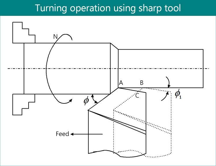
A close consideration to the figure can reveal that work material from triangle ABC will not be removed. With job revolution, this triangle ABC will repeat throughout the entire length and circumference of the job, which will ultimately lead to surface roughness. Therefore determination of height of triangle ABC is our main objective. It is worth noting that height of triangle ABC (that is minimum distance from finished surface to point C) is smaller than depth of cut (from practical point of view; otherwise it will be thread cutting instead of turning). Also points A and B will be very closer as feed rate is quite small (0.01 – 0.2mm/rev) compared to depth of cut (0.5 – 2mm).
So let us magnify the triangle ABC and redraw it as shown below. Mention the angles carefully. Angle A is equal to auxiliary cutting edge angle (φ1) while angle B is equal to principal cutting edge angle (φ) of the cutting tool. So DC is the maximum height of the lay marks, which is required to determine. It is quite simple, just consider two triangles (ADC and BDC) separately and apply trigonometric formula to incorporate feed rate.
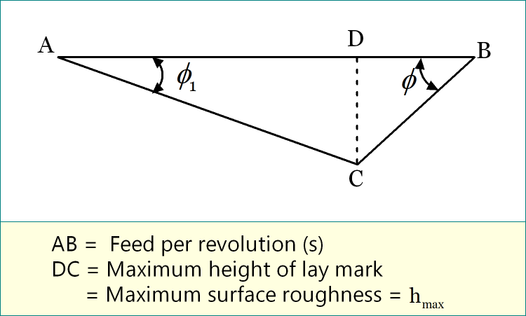
Step-1: From triangle ADC
cotφ1 = AD / DC
or, AD = DC × cotφ1
Step-2: From triangle BDC
cotφ = DB / DC
or, DB = DC × cotφ
Step-3: Incorporate feed rate
Feed rate per revolution = AB = AD + DB
or, s = AD + DB
or, s = (DC × cotφ1) + (DC × cotφ)
or, s = DC (cotφ1 + cotφ)
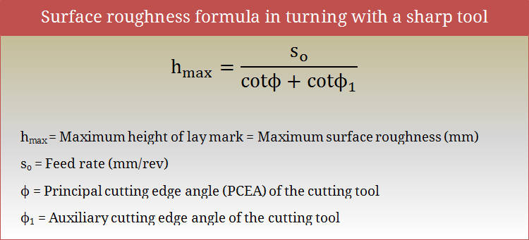
or, s = hmax (cotφ1 + cotφ)
or, hmax = s / (cotφ1 + cotφ)
References
- Book: Advances in Manufacturing Technology XV by D. T. Pham, S. S. Dimov and T. O’Hagan (Professional Engineering Publishing Limited).
- Proceedings: K. S. Umashankar, B. J. Manujesh and N. A. Jnanesh; Recurrence Qualification Analysis – A Tool to Analyze the Surface Finish During Machining; Advances in Mechanical Engineering; 2010.
- Book: Machining and Machine Tools by A. B. Chattopadhyay (Wiley).
- Book: Metal Cutting: Theory And Practice by A. Bhattacharya (New Central Book Agency).